


American DJ
®
INSTRUCTION MANUAL
DP-8A™ 8 CHANNEL DIMMING CONSOLE
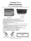
1. INDIVIDUAL CHANNELINDICATORS: yellow LED’s, indicating the lighting level of individual.
2. INDIVIDUAL CHANNEL SLIDERS: move to set the lighting level of channel.
3. INDIVIDUAL CHANNEL FLASH BUTTON: flash the individual channel channel full on.
4. MASTER SLIDER & INDICATOR: move to set the overall lighting level of all channels, red LED.
5. SPEED SLIDER & INDICATOR: slider to control speed, red LED indicating the chase speed.
6. FULL ON BUTTON: flash all channels to full on.
7. NEW FEATURE! SPEEDX2: speeds up chase two times when on.
8. POWER BUTTON
9. BLACK OUT BUTTON & INDICATOR: turns off all lights connected to console when turned on; red LED next to
button indicates on.
10. AUDIO BUTTON & INDICATOR: makes all lights connected to console Chase to the beat of the music by its
own internal microphone controller (sound active) when turned on; red LED next to button indicates on.
11. AUTO DIMMER BUTTON & INDICATOR: yellow LED indicates on.
12. NEW FEATURE! PROGRAM CONTROL: 10 different chase programs (numbers 0-10). Program “0” -
indicates “Manual Dimmer”. Programs “1 - 9” indicate 9 different chase programs.
13. AUDIO INPUT SOCKET: EXTERNALAUDIO CONTROL SIGNAL INPUT 100MV, 1/4” MONO JACK
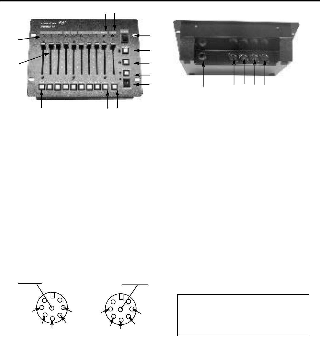
14. CH1 - CH4 OUTPUT SOCKET: 8 pin din socket; 0 - 10V signal output.
15. CH5 - CH8 OUTPUT SOCKET: 8 pin din socket; 0 - 10V signal output.
16. CH1 - CH4 OUTPUT SOCKET: 8 pin din socket; 0 - 10V signal output.
17. CH5 - CH8 OUTPUT SOCKET: 8 pin din socket; 0 - 10V signal output.
1
4
5
2
6
13 14 15 16 17
73
8
9
10
11
12
© American DJ® Los Angeles, CA 90058
FRONT VIEW
BACK VIEW
Specifications: model DP-8A™
3 lbs.
7” x 9.5” x 3”
1
2
G
3
4
5
6
G
7
8
DC +20V
DC +20V
FOR OUTPUT SOCKETS
CH1 - CH4 (# 14 & #16)
FOR OUTPUT SOCKETS
CH5 - CH8 (# 15 & #17)