American DJ®
User Instructions
Introduction:
Thank You and congratulations on your purchase
of the American DJ
®
Flash Tube Buffer™. This
buffer is a simple and easy way to extend the
range of your American DJ
®
Flash Matrix Hub™,
Flash-1C™, or Flash-2C™ Flash Tube™ controllers.
In some large venues it is sometimes necessary
to have extended cables run, due to the fact that
control booths are often located clear across the
room from any xtures. This buffer will prevent
any signal degradation that may occur after exces-
sively long cable runs.
Function:
Your different Flash Tube™ controllers (Flash
Matrix Hub™, Flash-1C™, or Flash-2C™) are
designed to handle total cable runs of 100ft. or
less. This total includes your Flash Tubes™ and/or
any extension cables. This buffer is designed to
boost the output signal of your controller. The
buffer is designed to be placed at the end of your
rst 100ft. run, not at the beginning. For Exam-
ple: If you have a fty foot extension cable run-
ning from your controller to 20 Flash Tubes™ (
Total
cable run of 150ft.
) the buffer must be placed after
the tenth Flash Tube™ which is about 100ft. 100ft.
is an approximate measurement, you may need
to place your buffer sooner in the line if are getting
erratic behavior.
Set-Up & Operation:
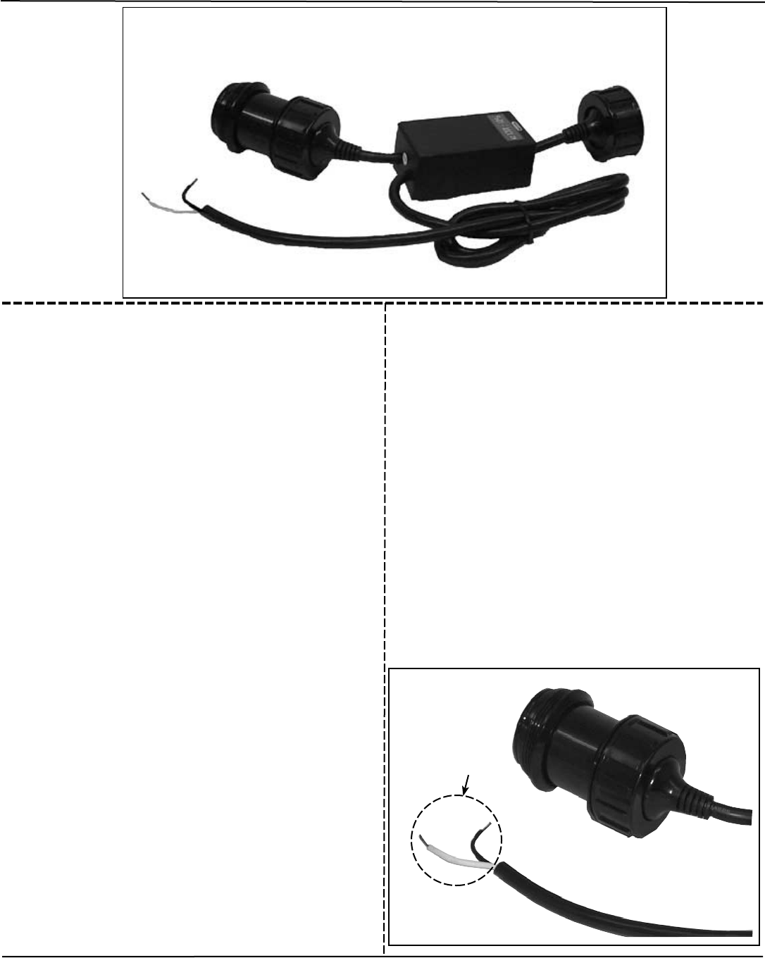
1. Your Flash Tube Buffer™ must be plugged
into a standard 120v Edison wall outlet. Please
install a standard 3 (three) prong electrical recep-
tacle to the exposed electrical wires (See Figure
1). Be sure to follow the manufactures guidelines
for proper installation of the electrical receptacle.
2. Connect the buffer in line with your system.
This will either be between two (2) Flash Tubes™
or between a Flash Tube™ and an extension
cable. Please note, there is two different types of
ends on the buffer an in and an out.
3. Plug your buffer into a 120v electrical outlet.
4.
Operate your Flash Tube™ controller as
directed.
Figure 1
Electrical Connection
©American DJ® Los Angeles Ca. 90058 - www.americandj.com - Flash Tube Buffer™
Flash Tube Buffer™


