


4
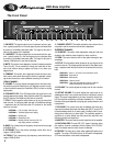
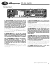
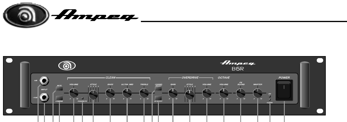
The Front Panel:
1. 0dB INPUT: The signal output from an instrument (active or pas-
sive – typically passive) or a line level signal may be connected here
by means of a shielded instrument cable. The signal at this jack is
sent into the preamp at full amplitude.
2. -15dB INPUT: The signal output from an instrument (active or pas-
sive – typically active) or a line level signal may be connected here
by means of a shielded instrument cable. The signal at this jack is
reduced 15dB before it is sent into the preamp.
3. MUTE: This switch, when depressed, mutes all outputs except the
Tuner Out (28). This is excellent for tuning your bass with an elec-
tronic tuner without having to adjust any levels or turn down your
stage volume.
4. COMBINE: This switch, when depressed, allows the clean chan-
nel to remain active when the overdrive channel is selected, combin-
ing the two channels to create a different-sounding “third channel.”
CLEAN CHANNEL:
5. VOLUME: This control adjusts the output level for the clean chan-
nel and the input to the Octave circuit (16). Adjust this control no high-
er than that which causes the Peak/Mute LED (6) to flash on strong
signal peaks.
6. PEAK/MUTE LED: This LED flashes when the signal level in the
preamp approaches clipping. When the Mute switch (3) is depressed,
this LED remains illuminated until the Mute is turned off.
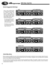
7. STYLE: This five-position switch allows you to vary the tone of the
clean channel. The following table lists each of the different settings
– experiment with the Style and other EQ controls for the results
which suit you best.
POSITION 1: Fully “scooped” mids (mid cut)
POSITION 2: Traditional passive tone setting
POSITION 3: Basically flat
POSITION 4: Boosted high end
POSITION 5: Basically flat with low end roll-off – for
loud playing without “muddiness”
8. BASS: This is the primary low frequency control which has a range
of 22dB @ 50Hz.
9. ULTRA MID: This is the primary midrange control which has a
range of 13dB @ 250Hz.
10. TREBLE: This is the primary high frequency control which has a
range of 22dB @ 8kHz.
11. CHANNEL SELECT: This switch selects the clean channel in the
out position and the overdrive channel when depressed.
OVERDRIVE CHANNEL:
12. OD BOOST: This switch, when depressed, adds gain and tone
shaping to the overdrive channel signal for heavy overdrive.
13. GAIN: This control sets the level of the signal entering the pre-
amp stage.
14. STYLE: This five-position switch allows you to vary the tone of the
overdrive channel. The following table lists each of the different set-
tings – experiment with the Style control for the results which suit you
best.
POSITION 1: Mid cut – for clean to semi-overdriven sound
POSITION 2: Slight mid cut
POSITION 3: Basically flat
POSITION 4: High end roll-off
POSITION 5: Large mid peak tailored for heavily overdriven
sound combined with the clean channel
15. VOLUME: This control adjusts the output level for the overdrive
channel.
16. OCTAVE VOLUME: This control adjusts the output level for an
added signal which is one octave lower than the instrument’s original
signal. This signal is dependent on the clean channel’s Volume con-
trol (5) and can be switched by the Octave footswitch (31). The effec-
tiveness of this signal depends on playing style, pickup selection, and
neck position.
17. FX BLEND: This control varies the mix between the direct (dry)
signal and the effects (wet) when the effects loop (26,27) is used. Full
counterclockwise results in all direct signal (no effect) and full clock-
wise gives all effect and no direct signal. The clockwise position is
equivalent to a series effects loop and should be used with such
devices as limiters and equalizers.
18. MASTER: This control sets the overall output level of the amplifier.
19. OD/CLEAN LEDS: The red LED (“OD,” upper) illuminates when
the overdrive channel is selected, while the green LED (“CLEAN,”
lower) illuminates when the clean channel is selected.
20. POWER: This heavy-duty rocker switch applies AC power to the
amplifier. The amp is ON when the top of the switch is depressed,
OFF when the bottom of the switch is depressed.
21 4 6 75 8 9 10 13 15 16 17 18143 1211 19 20
B5R Bass Amplifier