


• Specially engineered to meet the most critical acoustic
requirements of professional recording, broadcast and sound
reinforcement
• Direct-coupled, balanced output results in a clean signal even
under high-output conditions
• Transformerless circuitry virtually eliminates low-frequency
distortion and provides superior correlation of high-speed
transients
• Switchable 80 Hz hi-pass filter and 10 dB pad
• Rugged turned-brass microphone housing for enduring
dependability
• State-of-the-art design and manufacturing techniques ensure
compliance with A-T’s stringent consistency and reliability
standards
The AT4053b is intended for use in professional applications where
remote power is available. It requires 48V DC phantom power, which
may be provided by a mixer or console, or by a separate, in-line
source such as the Audio-Technica AT8801 single-channel or
CP8506 four-channel phantom power supplies.
Output from the microphone's XLRM-type connector is low
impedance (Lo-Z) balanced. The signal appears across Pins 2 and
3; Pin 1 is ground (shield). Output phase is “Pin 2 hot” – positive
acoustic pressure produces positive voltage at Pin 2.
To avoid phase cancellation and poor sound, all mic cables must be
wired consistently: Pin 1-to-Pin 1, etc.
An integral 80 Hz hi-pass filter provides easy switching from a flat
frequency response to a low-end roll-off. The high-pass position
reduces the microphone's sensitivity to popping in close vocal use.
It also reduces the pickup of low-frequency ambient noise (such
as traffic, air-handling systems, etc.), room reverberation and
mechanically coupled vibrations.
The AT4053b consists of two modular subassemblies: an AT4900b-48
body and an AT4053b-EL head capsule (both available separately).
Additional interchangeable capsules are available in omnidirectional
(AT4049b-EL) and cardioid (AT4051b-EL).
Avoid leaving the microphone in the open sun or in areas where
temperatures exceed 110° F (43° C) for extended periods. Extremely
high humidity should also be avoided.
Audio-Technica U.S., Inc., 1221 Commerce Drive, Stow, Ohio 44224
Audio-Technica Limited, Old Lane, Leeds LS11 8AG England
www.audio-technica.com
P52080 ©2008 Audio-Technica U.S., Inc. Printed inU.S.A.
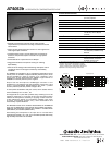
AT4053b
A
T4053b SPECIFICATIONS
†
ELEMENT Externally polarized
(DC bias) capacitor
P
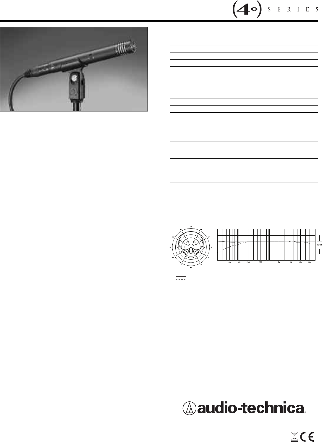
OLAR PATTERN Hypercardioid
FREQUENCY RESPONSE 20-20,000 Hz
L
OW FREQUENCY ROLL-OFF 80 Hz, 12 dB/octave
OPEN CIRCUIT SENSITIVITY –34 dB (19.9 mV) re 1V at 1 Pa*
I
MPEDANCE 50 ohms
MAXIMUM INPUT SOUND LEVEL 145 dB SPL, 1 kHz at 1% T.H.D.;
155 dB SPL, with 10 dB pad
(
nominal)
NOISE
1
16 dB SPL
D
YNAMIC RANGE (typical) 129 dB, 1 kHz at Max SPL
S
IGNAL-TO-NOISE RATIO
1
7
8 dB, 1 kHz at 1 Pa*
PHANTOM POWER REQUIREMENTS 48V DC, 4.8 mA typical
S
WITCHES Flat, roll-off; 10 dB pad (nominal)
WEIGHT (less accessories) 127 g (4.5 oz)
D
IMENSIONS 155.0 mm (6.10") long,
21.0 mm (0.83") maximum body
d
iameter
O
UTPUT CONNECTOR Integral 3-pin XLRM-type
ACCESSORIES FURNISHED AT8405a stand clamp for
5
/
8
"-27
threaded stands; windscreen;
protective carrying case
†In the interest of standards development, A.T.U.S.offers full details on its test
m
ethods to other industry professionals on request.
*1 Pascal = 10 dynes/cm
2
= 10 microbars = 94 dB SPL
1
Typical, A-weighted,using Audio Precision System One.
S
pecifications are subject to change without notice.
H
YPERCARDIOID CONDENSER MICROPHONE
200 Hz
5 kHz
1 kHz
8
kHz
SCALE IS 5 DECIBELS PER DIVISION
Polar Pattern
LEDEND
12" or more on axis
L
EGEND
R
oll-off
F
requency in Hertz
Frequency Response
Response in dB