


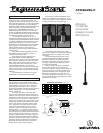
By removing an attached AT8533x power
module, the cable from the microphone can be
routed out the bottom of the microphone instead
of exiting from the side as supplied (Fig. 1).
The provided foam windscreen simply
slips over the head of the microphone, effectively
reducing wind noise or “popping” when used
extra close.
The small-diameter gooseneck is easy
to manipulate for proper positioning. Heavily
lubricated, it operates smoothly and quietly.
Should the unit become noisy with prolonged
use, apply a light machine oil directly on the
gooseneck area affected.
While a modern condenser microphone
is not unduly sensitive to the environment,
temperature extremes can be harmful. Exposure
to high temperature can result in gradual and
permanent reduction of the output level. Avoid
leaving the microphone in the open sun or in
areas where temperatures exceed 110° F (43° C)
for long periods of time. Extremely high humidity
should also be avoided.
AT935AMRx /C
Cardioid
Miniature
Condenser
Gooseneck
Adapter-mount
Microphone
Description
The AT935AMRx/C is a wide-range condenser
microphone with a cardioid polar pattern. It is
designed for quality sound reinforcement, profes-
sional recording, television, and other demanding
sound pickup applications. The small-diameter
gooseneck design permits highly flexible positioning
while maintaining a smooth, well-contoured
appearance. The AT935AMRx/C features a
5
/8"-27
threaded flange that allows it to mate with the
threads of a standard microphone desk or floor stand.
A
5
/8"-27 threaded stud is also provided so it can be
secured to a permanent mounting surface.
The microphone features an 11' (3.3 m)
permanently-attached miniature cable. Its free end
connects to the provided AT8533x power module
via internal solderless screw terminals for simple
cable-length adjustment in the field. It can be
powered from any external 9V to 52V DC phantom
power supply. A recessed switch in the power
module permits choice of flat response or
low-frequency roll-off to help control undesired
ambient noise.
Four additional interchangeable elements
are available to permit selection of angle of
acceptance from 90° to 360°.
Audio-Technica design engineers have
utilized the newest low-mass diaphragm
technology in the quest for superior performance.
The permanent charge is now on the fixed back
plate, rather than the moving element. With A-T
fixed-charge “back plate” construction, a gold-
vaporized diaphragm just 2 microns thick
(about .000079") can be used. This considerably
reduces moving mass, thus improving frequency
response and transient response while reducing
distortion.
The microphone is enclosed in a rugged
housing with a low-reflectance black finish.
Installation and Operation
Output is low impedance balanced. The
output connector of the power module mates
with XLRF-type cable connectors. The balanced
signal appears across Pins 2 and 3, while the
ground (shield) connection is Pin 1. Output is
phased so that positive acoustic pressure produces
positive voltage at Pin 2, in accordance with
industry convention.
To shorten the cable, remove the three
screws from the base of the power module and
slide the outer case up the cable to reveal the cir-
cuit board and screw terminals. Loosen the three
terminal screws and remove the cable from the
module. Next, slide the case off the cable, cut the
cable to the desired length (allowing a few extra
inches) and slide the case back onto the cable.
Tie a single knot in the cable about two inches
from the cut end. Following Figure 2, cut the
cable off 1" down from the top of the knot and
carefully remove
1
/2" of the outer jacket. Strip the
mic cable wires and attach them to their respec-
tive terminals (Fig. 3). Make certain that the termi-
nals are clamped on the conductors, not on the
insulation, and that there are no loose strands of
wire which might touch other terminals. Replace
the case, being certain that it goes
over
the case
grounding contact and that the roll-off switch is
accessible. Finish by replacing the three base
screws and testing for proper operation.
Figure 2
Shield strands,
fully twisted
Yellow-Yellow
Red-Red
1
/
8
" strip reds
and yellows
1
/
2
"
1"
Figure 3
Terminal
screws
Case
grounding
contact
Yellow-Yellow
Red-Red
Shield
PC board
switch side
SYR
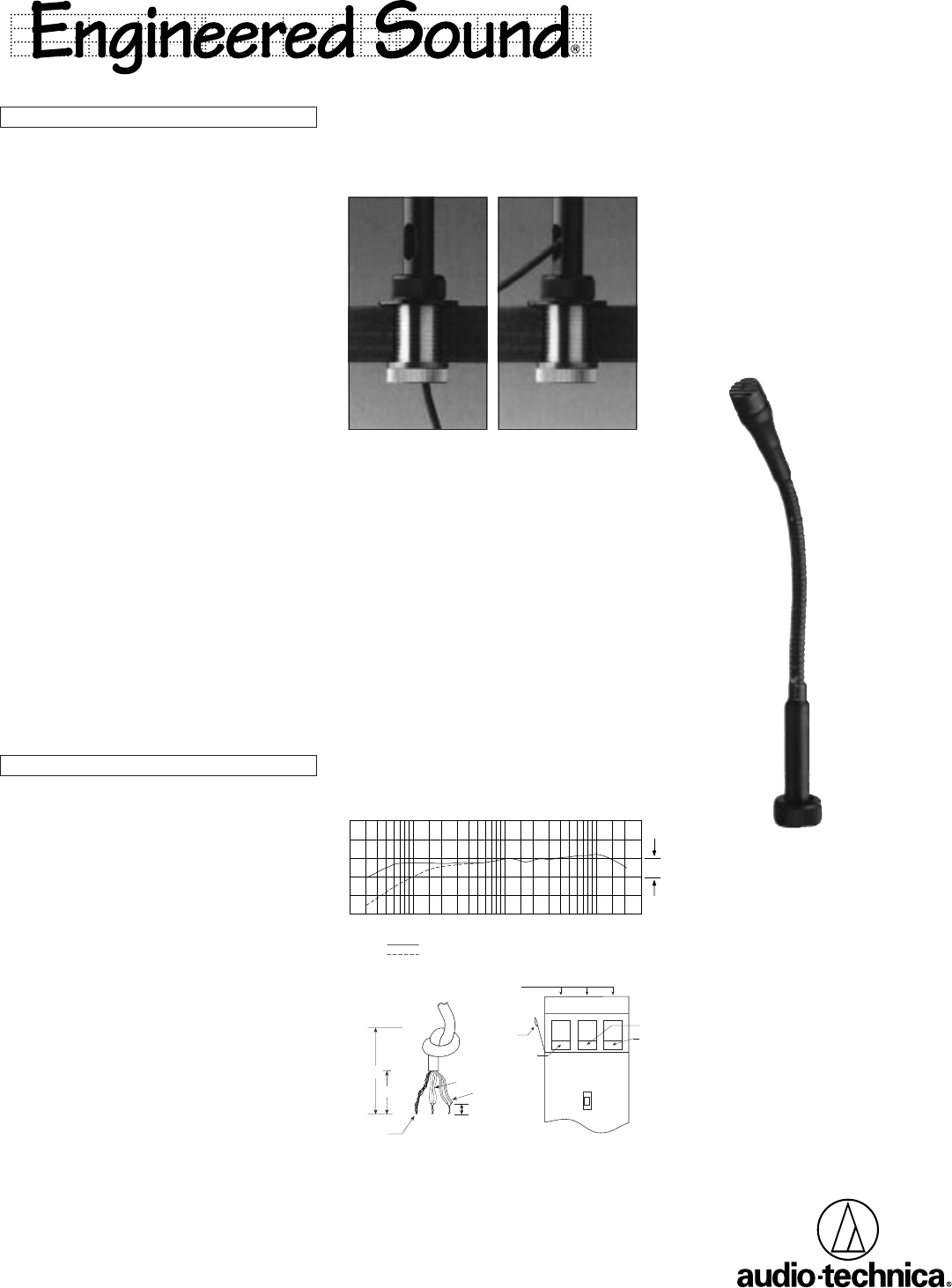
Frequency Response (Typical)
LEGEND
Roll-off
12" or more on axis (flat)
Frequency in Hertz
Response in dB
10 dB
20k
10k
5k
2k
1k
500
200100
50
Figure 1. Cable routing