•
Tailored response for musical instrument pickup–guitar cabinets,
snare and other percussion
•
Hypercardioid polar pattern reduces pickup of sounds from the
sides and rear, improving isolation of desired sound source
• Durable performance for professional applications
• Special dual-wall floating construction reduces handling noise and
assures consistent performance from mic to mic
• Hi-ENERGY
®
neodymium magnet for improved output and
transient response
• Multi-stage flat grille design is engineered to enable easy
placement as close as possible to sound source
• Corrosion-resistant contacts from gold-plated XLRM-type
connector
• Rugged, all-metal design and construction for years of trouble-free
use
Output from the microphone's XLRM-type connector is low
impedance (Lo-Z) balanced. The signal appears across Pins 2 and
3; Pin 1 is ground (shield). Output phase is “Pin 2 hot” – positive
acoustic pressure produces positive voltage at Pin 2.
To avoid phase cancellation and poor sound, all mic cables must be
wired consistently: Pin 1-to-Pin 1, etc. For a high-impedance (Hi-Z)
mic input, connect a Lo-Z balanced cable to a Hi-Z matching
transformer (A-T CP8201 or equal) at the equipment input.
When using the A
TM650 in settings with a stage monitor speak
er,
the speaker should be located 135° off axis (45° off the rear of the
microphone). This placement, in conjunction with the microphone's
uniform hypercardioid pickup pattern, will virtually eliminate the
possibility of undesired audio f
eedbac
k.
Take care to keep foreign particles from entering the windscreen. An
accumulation of iron or steel filings on the diaphragm, and/or foreign
material in the windscreen's mesh surface, can degrade
performance.
Note: Remove the rubber sleeve at the base of the microphone
handle to use the AT8471 isolation stand clamp (not included) for
more secure
, per
manent installation.
Audio-Technica U.S., Inc., 1221 Commerce Drive, Stow, Ohio 44224
Audio-Technica Limited, Old Lane, Leeds LS11 8AG England
www.audio-technica.com
P51805 ©2006 Audio-Technica U.S., Inc. Printed in China
ATM650
ATM650 SPECIFICATIONS
†
ELEMENT Dynamic
POLAR PATTERN Hypercardioid
FREQUENCY RESPONSE 80-17,000 Hz
OPEN CIRCUIT SENSITIVITY –56 dB (1.5 mV) re 1V at 1 Pa*
IMPEDANCE 300 ohms
WEIGHT 279 g (9.8 oz)
DIMENSIONS 164.2 mm (6.46") long,
38.8 mm (1.53") diameter
OUTPUT CONNECTOR Integral 3-pin XLRM-type
ACCESSORIES FURNISHED AT8470 Quiet-Flex
™
stand clamp
for
5
/
8
"-27 threaded stands;
5
/
8
"-27 to
3
/
8
"-16 threaded adapter;
soft protective pouch
†In the interest of standards development, A.T.U.S.offers full details on its test
methods to other industr
y professionals on request.
*1 Pascal = 10 dynes/cm
2
= 10 microbars = 94 dB SPL
Specifications are subject to change without notice.
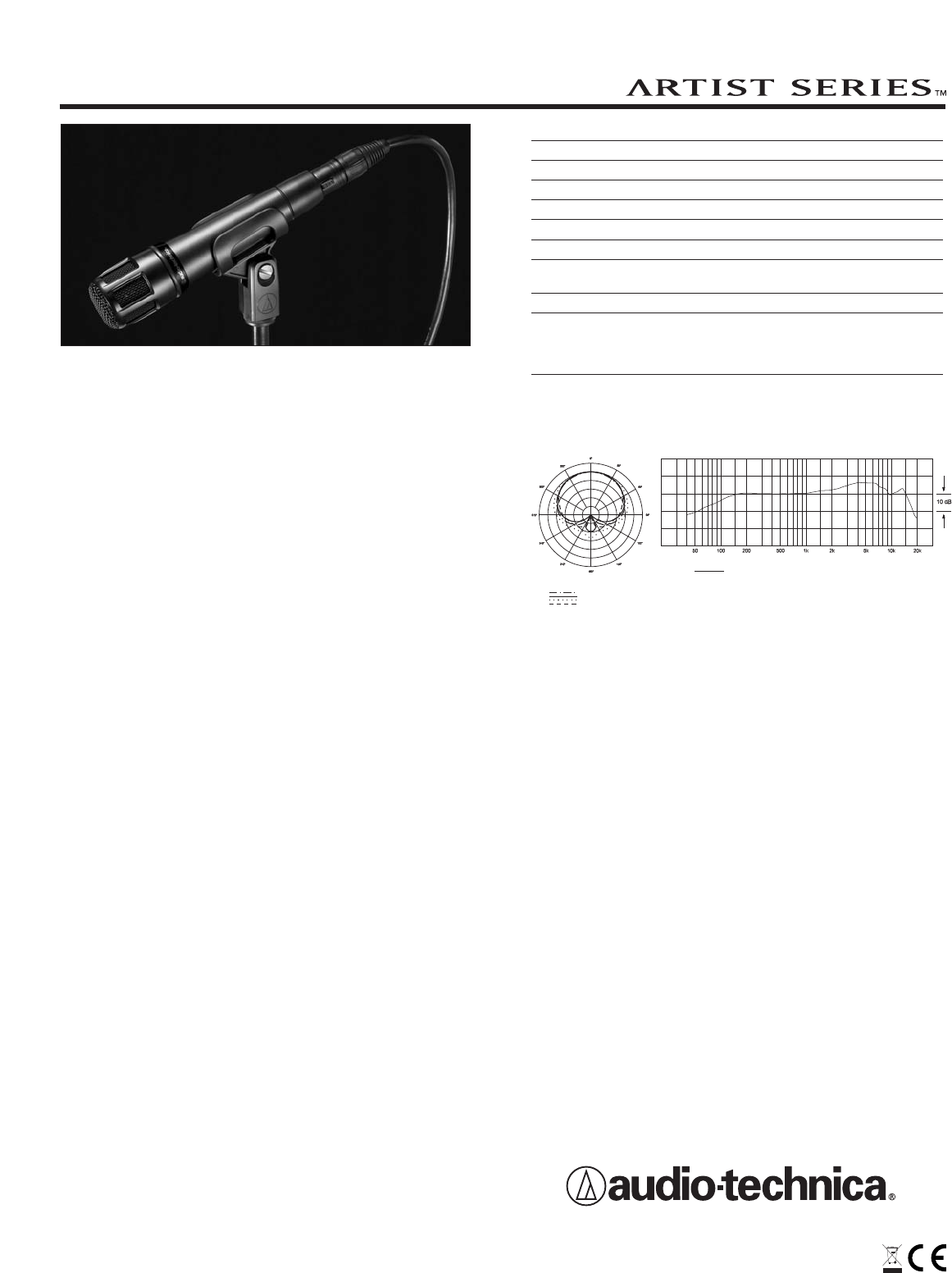
HYPERCARDIOID DYNAMIC
INSTRUMENT MICROPHONE
8 kHz
Polar Pattern
SCALE IS 5 DECIBELS PER DIVISION
LEGEND
200 Hz
1 kHz
5 kHz
Frequency in Hertz
LEGEND
12" or more on axis
Frequency Response
Response in dB


