engineered sound
®
microphones
Cardioid Condenser Gooseneck Microphones with Mute Switch/LED
ES915SC
Features
• Illuminating mute switch in the base lights when the microphone
is “on”
• Plugs into any standard XLRF-type connector, or direct mounts to
5
/8"-27 stands using included thread-mount adapter
• Low-prole element provides uniform cardioid polar pattern with
120º acceptance angle
• Superior off-axis rejection for maximum gain before feedback
• UniGuard
®
RFI-shielding technology offers outstanding rejection
of radio frequency interference (RFI)
• Easy-to-adjust, rugged, small-diameter, alternating gooseneck with
virtually no “memory” permits quick positioning into desired shape
• UniSteep
®
lter provides a steep low-frequency attenuation to
improve sound pickup without affecting voice quality
• Available interchangeable elements permit angle of acceptance
from 90º to 360º
• Included low-prole isolation mount attenuates noise, shock
and vibration
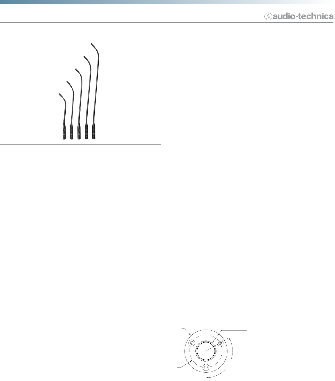
• Available in ve lengths
Description
The ES915SC is a wide-range miniature condenser microphone with a
cardioid polar pattern and an integral mute switch/LED. It is designed for
quality sound reinforcement, professional recording, television and other
demanding sound pickup applications.
The small-diameter double gooseneck design permits highly exible
positioning while maintaining a smooth, well-contoured appearance.
The ES915SC is available in the following models and lengths:
• ES915SC12: 304.8 mm (12.00")
• ES915SC15: 381.0 mm (15.00")
• ES915SC18: 457.2 mm (18.00")
• ES915SC21: 533.4 mm (21.00")
• ES915SC24: 609.6 mm (24.00")
The microphone requires 11V to 52V phantom power for operation.
The microphone is equipped with UniGuard
®
RFI-shielding technology,
which offers outstanding rejection of radio frequency interference (RFI).
The microphone’s cardioid polar pattern provides a 120° angle of acceptance.
Additional interchangeable elements with omnidirectional (360°),
hypercardioid (100°) and MicroLine
®
(90°) pickup patterns are available.
An XLRM-type connector insert at the base allows the microphone to be
plugged directly into an XLRF-type panel jack or microphone cable.
A recessed switch permits choice of at response or low-frequency roll-
off (via integral 80 Hz high-pass UniSteep
®
lter) to help control undesired
ambient noise. A mute switch in the base lights when the mic is “on.”
The mute switch is designed to operate quietly without any mechanical
noise.
The microphone comes equipped with a two-stage foam windscreen,
a low-prole isolation mount, and a stand clamp to permit attaching
the microphone to a standard
5
/8"-27 or
3
/8"-16 threaded mic stand or
mounting ange. The microphone is enclosed in a rugged housing with a
low-reectance black nish.
Installation and Operation
The ES915SC requires 11V to 52V phantom power for operation.
Output is low impedance (Lo-Z) balanced. The signal appears across Pins
2 and 3; Pin 1 is ground (shield). Output phase is “Pin 2 hot”— positive
acoustic pressure produces positive voltage at Pin 2.
The microphone can be mounted on a podium or desktop with the
included AT8474 low-prole isolation mount. Designed to be mounted
either above or beneath the mounting surface, the AT8474 rmly secures
the microphone while providing maximum attenuation of noise, shock
and vibration transmitted through the mounting surface. An AT8473 stand
clamp is also included to permit attaching the microphone to a standard
5
/8"-27 or
3
/8"-16 threaded mic stand or mounting ange.
The provided two-stage foam windscreen simply slips over the element,
effectively reducing wind noise and popping.
An integral 80 Hz high-pass UniSteep
®
lter provides easy switching
from a at frequency response to a low-end roll-off. The roll-off position
reduces the microphone’s sensitivity to popping in close vocal use. It
also reduces the pickup of low-frequency ambient noise (such as trafc,
air-handling systems, etc.), room reverberation and mechanically coupled
vibrations. To engage the UniSteep
®
lter, use the end tip of a paperclip
or other small pointed instrument to slide the switch toward the “bent” line.
Avoid leaving the microphone in the open sun or in areas where
temperatures exceed 110° F (43° C) for extended periods. Extremely high
humidity should also be avoided.
AT8474 Isolation Mount Installation Instructions
Mounting Dimensions
A. 1.5 mm (
1
/16") pilot holes 3 places on 40.0 mm (1.57") circle.
B. 25.4 mm (1.00") hole through the mounting surface.
C. Outside edge of mount, 52.4 mm (2.06") diameter.
1. The AT8474 mount can be mounted either above or below the
table surface.
2. Locate the center of the mounting location and mark it. Allow enough
clearance to accommodate the AT8474 mount on the desired
surface and make certain there are no physical obstructions
below the desired location.
3. Locate the three mounting screw holes and mark them.
4. Using a 1" hole saw, drill the through-hole for the microphone body.
(Note: Although a 1" drill bit will work, a hole saw provides for a cleaner
drawing not actual size
C
120°
A
B


