UniLine
®
Condenser Hanging Microphones
unipoint
®
microphones
U853PMU & U853PMWU
Features
• Wall/ceiling plate power module permits permanent installation
in standard, single-gang electrical box
• UniLine
®
polar pattern provides narrow 90º acceptance angle
• Low-prole design with low-reectance nish for minimum
visibility
• Superior off-axis rejection for maximum gain before feedback
• UniGuard
®
RFI-shielding technology offers outstanding rejection
of radio frequency interference (RFI)
• UniSteep
®
lter provides a steep low-frequency attenuation to
minimize pickup of undesired ambient noise
• Available interchangeable elements permit angle of acceptance
from 90º to 360º
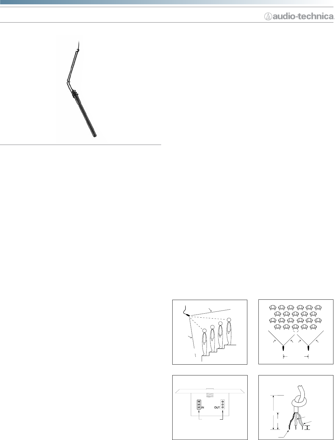
• Steel hanger positions microphone over choirs, instrumental
groups and theater stages
• Available in two colors: black (U853PMU) and white (U853PMWU)
Description
The U853PMU is a wide-range miniature condenser microphone with
a UniLine
®
(line cardioid) polar pattern. It is designed for quality sound
reinforcement, professional recording, television and other demanding sound
pickup applications. The combination of small size and excellent response
makes the microphone ideal for suspension over choirs, instrumental groups or
theater stages.
The microphone requires 11V to 52V phantom power for operation.
The microphone is equipped with UniGuard
®
RFI-shielding technology, which
offers outstanding rejection of radio frequency interference (RFI).
The microphone's UniLine
®
(line cardioid) polar pattern provides a 90° angle of
acceptance. Additional interchangeable elements with omnidirectional (360°),
cardioid (120°) and
hypercardioid (100°) pickup patterns are available.
The microphone includes a 7.6 m (25') permanently attached miniature cable.
Its free end connects to the provided AT8534 wall/ceiling plate power module
via a special TA3F-type connector designed to optimize RFI immunity. The
power module features a white-nished standard electrical cover plate for
easy, secure installation. Output connections on the power module are screw
terminals.
Switches in the power module permit a +10 dB gain setting for extra sensitive
pickup as well as a choice of at response or low-frequency roll-off (via integral
80 Hz high-pass UniSteep
®
lter) to help control undesired ambient noise.
The microphone comes equipped with a wall/ceiling plate power module,
a vinyl-coated steel hanger for positioning over a choir/orchestra/stage, a
two-stage foam windscreen and a
5
/
8
"-27 stand adapter. The microphone
is enclosed in a rugged housing with a low-reectance black nish. It is
also available with white housing, cable, hanger and windscreen as the
U853PMWU.
Installation and Operation
The U853PMU requires 11V to 52V phantom power for operation.
A uniform 90° angle of acceptance provides well-balanced audio pickup. The
microphone should be located forward of the front-most source, above the
rear-most source, and “aimed” between them (Fig.1). Increasing the height of
the mic above the sources will tend to equalize sound levels between them,
but may also increase background/reverberant sound pickup. When possible,
the distance from the mic to the rear-most source should be no more than
twice the distance to the front source, to maintain front-to-rear balance (Fig. 1).
Width of pickup is approximately 1.5 times the distance to the closest
performer. If additional mics are needed for wide sources, they should be
positioned apart laterally at least 1.5 times the distance to the front source,
to avoid phase cancellation (Fig. 2). To orient the microphone in the proper
direction, twist the housing slightly in its wire holder. (Clockwise rotation
moves the microphone to the right; counterclockwise rotation moves it to the
left.)
The provided two-stage foam windscreen simply slips over the head of the
microphone, effectively reducing noise from wind or ventilation air currents.
An integral 80 Hz high-pass UniSteep
®
lter provides easy switching from a
at frequency response to a low-end roll-off. The roll-off position reduces the
pickup of low-frequency ambient noise (such as trafc, air-handling systems,
etc.), room reverberation and mechanically coupled vibrations. To engage the
UniSteep
®
lter, slide the switch toward the “bent” line. A 10 dB gain switch
is provided for situations that demand extra sensitive pickup. The +10 position
increases the microphone's overall output by 10 dB. To engage the 10 dB gain,
slide the switch toward the +10 position.
The AT8534 wall/ceiling plate power module is designed to be mounted
in a standard metal U.S. single-gang electrical box. For safety and best
performance, use the electrical box only for the AT8534; do not include any AC
power conductors. (Also route the mic cable as far away from AC power cables
as possible.)
Screw-terminal output connections of the AT8534 are the same as those
of an XLR-type plug: shield to Terminal 1, balanced signal and phantom
power to Terminals 2 and 3. Output is phased so that positive acoustic
pressure produces positive voltage at Terminal 2, in accordance with industry
convention. Do not connect the output cable shield to the box. Double-
check to make certain that all input and output leads have no bare wires or
loose strands that could touch each other, the circuit board or the electrical box.
Then attach the power module plate to the electrical box.
MIC A
1.5 TIMES
DISTANCE “X”
MIC B
90
°
90
°
v+
SIG
GND
3
2
1
Terminal screws
RED/
RED
YEL / YEL
SHIELD
INPUT
AUDIO -
AUDIO +
SHIELD
OUTPUT
Shield strands,
fully twisted
Yellow-Yellow
Red-Red
1
/
8
" strip reds
and yellows
1
/
2
"
1"
Figure 1 Figure 2
Figure 3 Figure 4
L
ES
S
T
H
AN 2 TIMES
“X
”
D
IS
T
A
N
CE
“
X
”
90°
ANGLE OF
ACCEPTANCE


