• Designed for suspension over
choirs, instrumental groups
and theater stages
• UniLine
™
polar pattern
provides narrow 90°
acceptance angle
• Superior off-axis rejection for
maximum gain before
feedback
• UniGuard
™
RFI-shielding
technology offers outstanding
rejection of radio frequency
interference (RFI)
• UniSteep
®
filter pro
vides a
steep low-frequency
attenuation to improve sound
pickup without affecting voice
quality
• Accepts interchangeable
elements to permit angle of
acceptance from 90° to 360°
• Low-profile design with low-reflectance finish for minimum
visibility
• Available in two colors: black (U853RU) and white (U853RWU)
The U853RU requires 11V to 52V phantom power for operation.
A uniform 90° angle of acceptance provides well-balanced audio
pickup over a narrow area. The microphone should be located
forward of the front-most source, above the rear-most source, and
“aimed” between them (Fig.1). Increasing the height of the mic
above the sources will tend to equalize sound levels between them,
but may also increase background/reverberant sound pickup. When
possible, the distance from the mic to the rear-most source should
be no more than twice the distance to the front source
, to maintain
front-to-rear balance (Fig. 1).
Width of pickup is approximately 1.5 times the distance to the
closest performer. If additional mics are needed for wide sources,
they should be positioned apart laterally at least 1.5 times the
distance to the front source, to avoid phase cancellation (Fig. 2).
To orient the microphone in the proper direction, twist the housing
slightly in its wire holder. (Clockwise rotation moves the microphone
to the right; counterclockwise rotation moves it to the left.)
Output from the power module’s XLRM-type connector is low
impedance (Lo-Z) balanced. The signal appears across Pins 2 and
3; Pin 1 is ground (shield). Output phase is “Pin 2 hot” – positive
acoustic pressure produces positive voltage at Pin 2.
An integral 80 Hz high-pass UniSteep
®
filter provides easy switching
from a flat frequency response to a low-end roll-off. The
roll-off position reduces the pickup of low-frequency ambient noise
(such as traffic, air-handling systems, etc.), room reverberation and
mechanically coupled vibr
ations.
Avoid leaving the microphone in the open sun or in areas where
temperatures exceed 110° F (43° C) for extended periods.
Extremely high humidity should also be avoided.
NOTE: Audio-Technica has developed a special RFI-shielding
mechanism, which is an integral part of the connectors in the
UniPoint line. If you remove or replace the connector, you may
adversely affect the unit's RFI immunity.
Fréquence - Hertz
LÉGENDE
12" ou plus sur l'axe
Pente de diminution
Réponse en Fréquence
Réponse - dB
8 kHz
200 Hz
1 kHz
5 kHz
Directivité
ÉCHELLE: 5 dB PAR DIVISION
LÉGENDE
Audio-Technica U.S., Inc., 1221 Commerce Drive, Stow, Ohio 44224
Audio-Technica Limited, Old Lane, Leeds LS11 8AG Angleterre
www.audio-technica.com
P51697 ©2005 Audio-Technica U.S., Inc. Imprimé aux E.U.
8 kHz
Polar Pattern
SCALE IS 5 DECIBELS PER DIVISION
LEGEND
200 Hz
1 kHz
5 kHz
F
requency in Hertz
LEGEND
12" or more on axis
Roll-off
Frequency Response
Response in dB
Audio-Technica U.S., Inc., 1221 Commerce Drive, Stow, Ohio 44224
Audio-Technica Limited, Old Lane, Leeds LS11 8AG England
www.audio-technica.com
P51697 ©2005 Audi
o-Technica U.S., Inc. Printed in U.S.A.
U853RU / U853RWU
U853R
U/U853RWU SPECIFICATIONS
†
ELEMENT Fixed-charge back plate
per
manently polarized
condenser
POLAR P
ATTERN
Line Cardioid
FREQ
UENCY RESPONSE
30-20,000 Hz
LO
W FREQUENCY ROLL-OFF
80 Hz, 18 dB/octa
ve
OPEN CIRCUIT SENSITIVITY –35 dB (17.7 mV) re 1V at 1 P
a*
IMPED
ANCE
250 ohms
MAXIMUM INPUT SOUND LEVEL 135 dB SPL, 1 kHz at 1%
T.H.D.
D
YNAMIC RANGE
(typical)
115 dB, 1 kHz at Max SPL
SIGNAL-TO-NOISE RATIO
1
74 dB, 1 kHz at 1 Pa*
PHANT
OM POWER REQUIREMENTS
11-52V DC
, 2 mA typical
SWITCH Flat, roll-off
WEIGHT
MICR
OPHONE
1.1 oz (30 g)
POWER MODULE 2.9 oz (81 g)
DIMENSIONS
MICR
OPHONE
6.14" (156.0 mm) long,
0.48" (12.2 mm) diameter
PO
WER MODULE
3.66" (92.9 mm) long,
0.74" (18.9 mm) diameter
OUTPUT CONNECTOR Integral 3-pin XLRM-type
(power module)
CABLE 25.0' (7.6 m) long (per
manently
attached to microphone), 0.13"
(3.2 mm) diameter
, 2-conductor,
shielded cab
le with TA3F-type
connector
OPTIONAL INTERCHANGEABLE UE-C cardioid (120°);
ELEMENTS UE-H h
ypercardioid (100°);
UE-O omnidirectional (360
°)
A
CCESSORIES FURNISHED
U853R
U
A
T8154 two-stage foam
windscreen;
AT8451 steel hanger
U853RWU AT8154(WH) two-stage foam
windscreen; AT8451(WH) steel
hanger
BO
TH
A
T8538 power module;
A
T8438
5
/
8
"-27 stand adapter
†
In the interest of standards de
velopment, A.T.U.S.offers full details on its test
methods to other industry professionals on request.
*1 Pascal = 10 dynes/cm
2
= 10 microbars = 94 dB SPL
1
T
ypical, A-weighted, using Audio Precision System One.
Specifications are subject to change without notice.
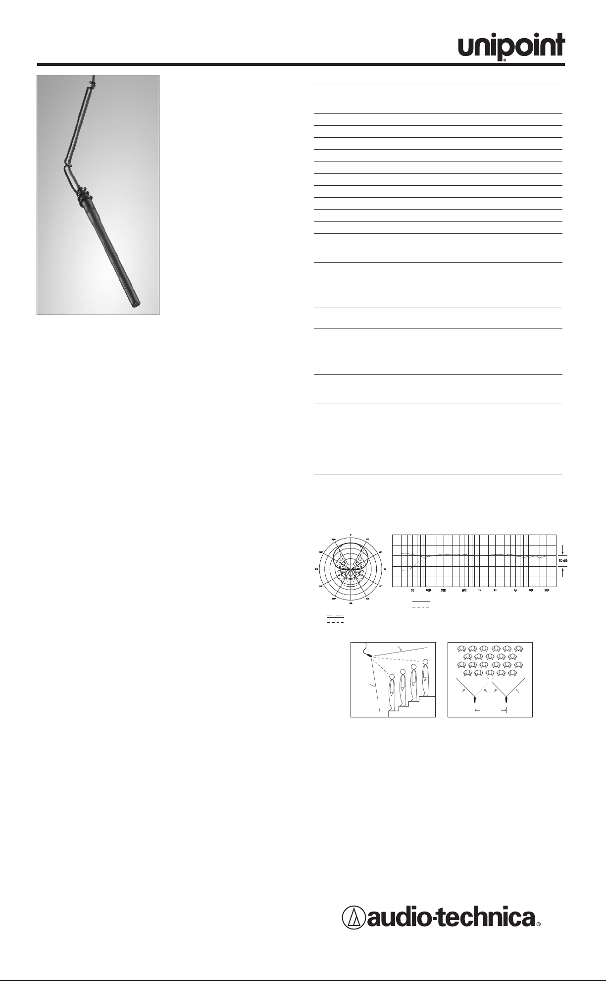
UNILINE
™
CONDENSER
HANGING MICROPHONES
• Conçus pour être suspendus
au-dessus des chœurs, des
groupes instrumentaux et des
scènes de théâtre
• Directivité UniLine
™
fournissant un angle
d’acceptance étroit de 90°
• Rejet hors axe supérieur pour
un gain avant accrochage
maximal
• Excellent rejet des
interférences rf
• Filtre UniSteep
®
pour une forte
atténuation des basses
fréquences ; améliore la prise
de son sans affecter la qualité
de la voix
• Peut recevoir des capsules
interchangeables, ce qui
permet d’avoir un angle
d’acceptance allant de 90°
à 360°
• Design discret avec une finition minimisant les reflets pour une
visibilité minimale
• Disponible dans deux couleurs : noir (U853RU) ou blanc
(U853RWU)
Le U853RU fonctionne sur alimentation fantôme de 11V à 52V.
La prise de son est bien équilibrée sur une zone étroite grâce à un
angle d’acceptance uniforme de 90°. Le microphone doit être placé
en avant de la source la plus en avant, et au-dessus de la source la
plus en arrière, et doit être dirigé vers un point situé entre ces deux
sources (Fig. 1). Plus on élève le micro au-dessus des sources,
plus on égalise les niveaux acoustiques entre l’avant et l’arrière ;
cepedant, les bruits de fond et de réverbération risquent d’être
davantage perceptibles. Pour préserver un équilibre entre la prise
de son avant et arrière, la distance entre le micro et la source
sonore la plus en arrière ne doit pas excéder le double de la
distance qui sépare le micro de la source la plus en avant (Fig. 1).
La largeur de la prise de son est égale à environ 1,5 fois la distance
qui sépare le micro de l’interprète le plus proche. Si vous avez
besoin de rajouter des micros pour les sources “larges”, les micros
doivent être placés sur une même ligne, à une distance les uns des
autres d’au moins 1,5 fois la distance qui les séparent de la source
la plus en avant, pour éviter une annulation de la phase (Fig. 2).
Pour orienter le microphone dans la bonne direction, tournez
légèrement le corps du microphone dans son support métallique
(une rotation dans le sens des aiguilles d’une montre pour l’orienter
vers la droite, dans le sens inverse des aiguilles d’une montre pour
l’orienter vers la gauche).
La sortie du module d’alimentation est symétrique basse
impédance, elle se fait sur une embase XLRM 3 broches. Le signal
symétrique est entre les broches 2 et 3, le point chaud est en deux
(la tension positive sur le point chaud est générée par une pression
acoustique positive sur la capsule). La masse (blindage) est sur la
broche 1.
Un filtre passe-haut 80 Hz intégré UniSteep
®
permet de passer
facilement de la réponse en fréquences plate à l’atténuation des
raves. La position passe-haut sert à réduire la sensibilité aux bruits
ambiants de basse fréquence (dus au trafic, aux installations de
ventilation, etc.), à la réverbération de la pièce et aux vibrations
couplées mécaniquement.
Evitez de laisser le microphone en plein soleil ou dans des endroits
où la température est supérieure à 43°C (110°F) pendant une
durée prolongée. Une trop forte humidité doit également être
évitée.
REMARQUE : Audio-Technica a développé un dispositif spécial
d'écran RFI faisant intégralement partie des connecteurs dans la
ligne UniPoint. Si vous retirez ou replacez le connecteur, vous
pouvez affecter l'immunité vis-à-vis du brouillage radioélectrique.
U853RU / U853RWU
U853RU/U853RWU CARACTÉRISTIQUES TECHNIQUES
†
TYPE Condensateur polarisé en
permanence avec plaque fixe à
charge fixe
DIRECTIVITÉ Cardioïde-ligne
RÉPONSE EN FRÉQUENCE 30-20 000 Hz
ATTÉNUATION DES GRAVES 80 Hz, 18 dB/octave
NIVEAU DE SORTIE –35 dB (17,7 mV) réf 1V/Pa*
IMPÉDANCE 250 ohms
NIVEAU DE PRESSION 135 dB SPL, 1 kHz à 1% T.H.D.
ACOUSTIQUE MAXIMAL
DYNAMIQUE (typique) 115 dB, 1 kHz à SPL max.
RAPPORT SIGNAL/BRUIT
1
74 dB, 1 kHz/Pa*
ALIMENTATION FANTÔME 11-52V CC, 2 mA typiques
COMMUTATEUR Plat, atténuation
POIDS
MICROPHONE
30 g (1,1 oz)
MODULE D’ALIMENTATION 81 g (2,9 oz)
DIMENSIONS
MICROPHONE
Longueur 156,0 mm (6,14 po),
diamètre 12,2 mm (0,48 po)
MODULE D’ALIMENTATION Longueur 92,9 mm (3,66 po),
diamètre 18,9 mm (0,74 po)
CONNECTEUR DE SORTIE Type XLRM 3 broches intégré
(module d’alimentation)
CÂBLE Câble blindé à 2 conducteurs, de
3,2 mm de diamètre (0,13 po) et
7,6 m de long (25,0 pi) (solidaire
du microphone), avec connecteur
de sortie TA3F
CAPSULES INTERCHANGEABLES UE-C cardioïde (120°);
EN OPTION UE-H hypercardioïde (100°);
UE-O omnidirectionnel (360°)
ACCESSOIRES FOURNIS
U853RU
AT8154 bonnette anti-vent en
mousse double épaisseur;
AT8451 suspension en acier;
U853RWU AT8154(WH) bonnette anti-vent
en mousse double épaisseur;
AT8451(WH) suspension en acier;
LES DEUX AT8538 module d’alimentation;
AT8438 adaptateur pour pied
5
/
8
"-27
†
Afin de contribuer au développement des normes, A.T.U.S.fournit tout renseignement sur
ses méthodes de test aux professionnels de l’industrie qui en font la demande.
*1 Pascal = 10 dynes/cm
2
= 10 microbars = 94 dB SPL
1
Typique, pondéré en A, mesuré avec l’Audio Precision System One.
Les caractéristiques techniques sont soumises à des changements sans préavis.
MICROPHONES SUSPENDUS
À CONDENSATEUR UNILINE
™
LESS THAN 2 TIMES “X”
DIST
ANCE “X”
90°
ANGLE OF
ACCEPTANCE
Figure 1
MIC A
1.5 TIMES
DISTANCE “X”
MIC B
90°90°
Figure 2
LESS THAN 2 TIMES “X”
DISTANCE “X”
90°
ANGLE OF
ACCEPTANCE
Figure 1
MIC A
1.5 TIMES
DISTANCE “X”
MIC B
90°90°
Figure 2


