


5
ULTRAGRAPH PRO FBQ1502/ULTRAGRAPH PRO FBQ3102/ULTRAGRAPH PRO FBQ6200
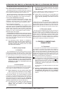
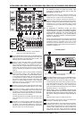
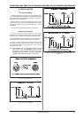
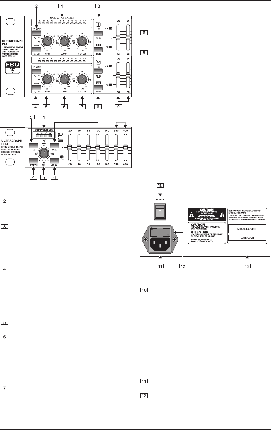
Fig. 2.1: Front panel control elements of the FBQ3102
(above) and of the FBQ1502 (below)
The I/O METER IN/OUT switch lets you alternate between
displaying the input and the output signal level. When the
switch is depressed, the output signal level is shown. The
FBQ1502 does not feature this switch.
When you press the FBQ switch, the FBQ feedback
detection system is activated. The frequency (or frequen-
cies) that evoke feedback is/are indicated by means of a
lighted fader LED. All other LEDs are toned down. Now,
simply lower the respective frequency range somewhat
until you eliminate the feedback and the LED no longer
lights up.
The AUDIO IN/OUT switch is used to enable or disable the
entire equalizer section. The FBQ1502 does this
electronically, while the FBQ3102 and the FBQ6200 feature
a relay-driven hard bypass function. As long as the switch
is not depressed or while the equalizer is not powered up,
the inputs and the outputs are directly connected to one
another. The AUDIO IN/OUT switch is used to alternate
between A and B, i.e. to compare the original unprocessed
signal with the processed signal.
The INPUT control is used to adjust the input signal level.
You can boost/attenuate the signal level from +15 to -15 dB.
The LOW CUT control is used to adjust the lower cut-off
frequency of your ULTRAGRAPH PRO. The high-pass filter
(18 dB/oct.) covers the range between 10 and 400 Hz,
whereby the filter lets the signal pass through unprocessed,
when the control is in the 10 Hz position.
The FBQ1502 features a switchable high-pass filter (LOW
CUT) instead of a low cut control, and its cut-off frequency
is 25 Hz.
The HIGH CUT control is used to adjust the upper cut-off
frequency of your ULTRAGRAPH PRO. The low-pass filter
(18 dB/oct.) covers the range between 2.5 and 30 kHz,
whereby the filter lets the signal pass through unprocessed
when the control is in the 30 kHz position.
+ Use the high-pass and low-pass filters to define
the frequency range you wish to process. This
provides you with an efficient way to limit the
bandwidth you work with.
The RANGE switch lets you alternate between the
maximum value of lowering/increasing of individual
frequencies from 12 dB to 6 dB (switch depressed).
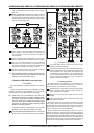
These are the 31 SLIDING CONTROLS (FBQ1502: 15
sliding controls per channel) for individual frequency bands.
When in 0 position, the particular frequency range is not
processed at all. To boost a frequency range, pull the
sliding control upward; to attenuate, pull the sliding control
downward.
+ To emphasize a frequency range, you dont
necessarily have to move its respective sliding
control upward; try lowering surrounding frequency
ranges instead. This way, you avoid causing the
next piece of equipment in your sound path to
overdrive. You also preserve valuable dynamic
reserve (headroom).
Sliding controls feature LEDs that indicate the signal level
of their particular frequency ranges through their varying
illumination intensity: what better way to show critical
frequencies that evoke feedback. How to best use your
ULTRAGRAPH PRO to detect these critical frequencies is
described in chapter 3.2.1.
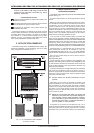
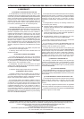
2.2 Rear panel
Fig. 2.2: Control elements and important information on the
rear of the FBQ3102
The POWER switch powers up your ULTRAGRAPH PRO.
The POWER switch should always be in the Off position
when you are about to connect your FBQ to the mains.
To disconnect the unit from the mains, pull out the main cord
plug. When installing the product, ensure that the plug is
easily accessible. If mounting in a rack, ensure that the
mains can be easily disconnected by a plug or by an all-pole
disconnect switch on or near the rack.
+ Please keep in mind: The POWER switch does not
entirely separate the unit from the mains. Please
disconnect the power cord from the mains if you
will not be using your FBQ for longer periods of
time.
FBQ1502s power switch is located at the front.
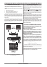
The connection to the mains is done via a standard IEC
connector. A matching cable is included.
FUSE COMPARTMENT / VOLTAGE SELECTION. Before
connecting the unit to a power outlet, please make sure
that the selected voltage matches your local voltage. When
replacing fuses, please make sure that you always use
fuses of the same type. Some units allow for switching
between 230 V and 120 V. Please note: when connecting
2. CONTROL ELEMENTS AND CONNECTORS