


6
ULTRAGRAPH PRO FBQ1502/ULTRAGRAPH PRO FBQ3102/ULTRAGRAPH PRO FBQ6200
a unit intended for the European market to a 120 V power
outlet, you must also replace the factory fuse with a higher-
value fuse.
SERIAL NUMBER. Please take a few minutes and send to
us a completely filled out warranty card within 14 days of
the original date of purchase. Otherwise, warranty claims
may be rendered invalid. Or fill out the warranty information
online at www.behringer.com.
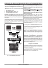
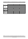
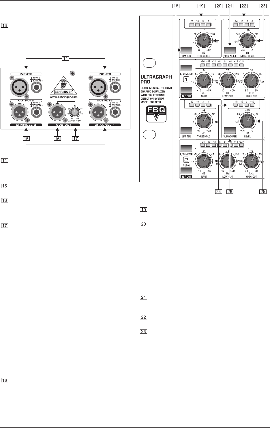
Fig. 2.3: Connectors at the rear of the FBQ3102
INPUT. These are the audio inputs of the FBQ3102. All
three equalizers in the series feature the same input and
output connectors in the form of balanced 1/4" TRS and
XLR connectors.
OUTPUT. These are the audio outputs. The 1/4" connectors
and their respective XLR connectors are wired in parallel.
SUB OUT. This balanced XLR connector provides the
output signal for your subwoofer. A summed up mono
signal for the subwoofer is provided here. Please connect
the subwoofer amplifiers input to this connector.
Use the X-OVER FREQ control to select the desired
crossover frequency for the subwoofer.
+ The bandwidth limitation enacted through the high-
pass filter (LOW CUT) also affects the frequency
response of the subwoofer output.
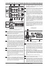
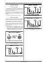
2.3 Additional FBQ6200 control elements
2.3.1 Limiter
One of the FBQ6200s outstanding features is its integrated
limiter.
A limiter is a device that protects your loudspeakers and other
equipment connected to your FBQ6200 (or your recordings)
from overdriving and the signal distortion associated.
+ Please take into consideration that when you
increase the presence of multiple frequency bands,
the overall signal level increases substantially as
well. The limiter will process very quickly in such
situations. This can be avoided by performing signal
corrections by lowering certain frequency ranges
instead of increasing others.
To produce creative sound effects, you can also
purposely force the peak limiter into action.
The ULTRAGRAPH PRO FBQ6200 features a built-in limiter
for each channel. Use the LIMITER switch for its activation.
Fig. 2.4: FBQ6200 control elements
The limiter display informs you about the amount of gain
reduction perfomed by the limiter.
The limiter confines the signal to an adjustable signal level.
Use the THRESHOLD control to adjust the threshold value
of the limiter from -6 to +22 dB. When the control is in the
-6 dB setting, the gain reduction is very pronounced; the
more you turn the control toward +22 dB, the gain reduction
is lower. When the threshold control is in its right-most
position, the limiter is not applied.
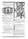
2.3.2 Noise generator
By using the built-in noise generator, you can create the so-
called pink noise that can be used to adjust your P.A. system to
specific acoustic characteristics of various venues.
Activate the pink noise generator by using the PINK NOISE
switch. The built-in switch illumination blinks red when the
pink noise generator is activated.
Read off the noise generators signal level on the LED
display.
Use the NOISE LEVEL control to adjust the volume of the
pink noise you generate.
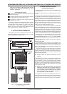
Room resonance and sound transfer characteristics of the
P.A. system cause some frequencies to be more prominently
present while other frequencies are less present. Pink noise is a
neutral signal that can be played back via the P.A. system in
order to measure these sound characteristics.
Such a measurement of the frequency response by using a
special microphone in conjunction with a real-time analyzer (a
real-time analyzer is for example integrated into the BEHRINGER
ULTRACURVE PRO DEQ2496) delivers the basis for setting up
the equalizer. More pronounced frequencies are lowered, and
those frequencies that are not so prominently featured are
increased, thus approximately achieving linear reproduction.
2. CONTROL ELEMENTS AND CONNECTORS