


14
U-CONTROL UMA25S
5.4 Assignment of control messages
in Edit Mode
It is possible to specify settings that are different from the presets.
To do so, you need to determine which control elements on the
UMA25S generate which MIDI messages.
You need to specify how the incoming controllers are to be
interpreted on the slave unit. At this point, we suggest you refer
to the user manual of the slave unit.
General assignment of control messages in Edit Mode:
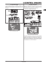
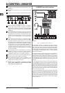
1. Press and hold down the EDIT/EXIT push button. The device
switches to Edit Mode and “Edt” appears on the display.
2. Use the control element you want to edit. The name of the
control shows up on the display (for example, “E10”).
3. Release the EDIT/EXIT push button. Its LED lights up.
4. Use the rotary knobs E9 – E16 to assign the MIDI messages
to the selected control element. The applicable MIDI
messages and their descriptions are found in the tables of
Chapter 5.5.
In case you want to check the current parameter
settings, press the push button (E1 – E8) found
under the rotary knob whose function you want to
examine. As soon as the push button is pressed,
the settings appear on the display for a short time.
Alternatively, use the Show Element function (see
Chapter 5.6.1).
5a. Press the ENTER key to confirm. The EDIT LED goes out.
5b. Alternatively, press the EDIT/EXIT push button to cancel
the changes and exit Edit Mode. The EDIT LED goes out.
All settings made with this function are stored
temporarily! If you want to store the settings
permanently, save them in a preset (see Chapter
5.1.2).
The various MIDI functions are described in detail in Chapter 5.5.
Comments on Step 4:
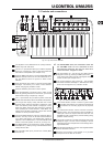
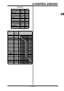
In Edit Mode, all settings are made by turning the knobs E9 – E16.
The available setting options depend on the data types being
used.
E9 E10 E11 E12 E13 E14 E15 E16
MIDI
Data
Type
MIDI
Send
Channel
Parameter
Value
1
Value
2
Controller
Mode
Controller
Option
Display
Value
Table 5.1: General assingment of rotary knobs in Edit Mode
MIDI Data Type:
The E9 rotary knob lets you select the message type that is to
be assigned to a control element. Refer to Chapter 5.5 for
information on MIDI messages.
MIDI Send Channel:
The E10 rotary knob allows you to select the MIDI channel on
which the message is supposed to be sent. When Channel 0 is
selected, the message is sent on the GLOBAL SEND CHANNEL
(see Chapter 5.7).
Parameter, Value 1, Value 2:
The rotary knobs E11 to E13 allow you to adjust the parameters
and the corresponding values of the selected MIDI message.
The parameters vary according to the MIDI message (see
Chapter 5.5).
Controller Mode:
The E14 rotary knob is provided to determine the switch
behavior of the selected control element. This option is only
available for switch elements (push buttons).
The control push buttons support the controller modes “Toggle
On”, “Toggle Off” and “Increment”. Toggle On is comparable to
a switching function (for example, the light switch of a room).
The “On” value, which is specified with the E12 rotary knob
(value 1), is sent by pressing the push button the first time.
Press the push button a second time to send the “Off” value,
which is specified with the E13 rotary knob (value 2). This setting
is ideal for triggering drumloops from a sampler (press once =
Start, press a second time = Stop).
Toggle Off corresponds to a push button function, which is
comparable to the switch of an electric door opener. The On
value (value 1) is sent by pressing the push button. The Off
value (value 2) is sent by releasing the push button. You should
use this mode when triggering short sound effects and samples
(similar to playing a keyboard).
The Increment option is only available for the messages
Program Change, CC, NRPN and After Touch. This mode allows
a stepwise increment of the controller value each time the push
button is pressed. Use E15 to adjust the step interval.
Controller Option:
Select the controller mode “Increment” to determine the step
interval of the push buttons by using the E15 rotary knob. This
means that each time you press one of the push buttons, the
transmitted value is increased by the step interval you specified
in advance. If the step interval is set to “10,” values 0, 10, 20,
30 ... 110, 120, 0, 10, etc. are sent one after another. You can
also enter negative values (for example, -10) to achieve a gradual
decrement. In case you have specified the lowest and highest
transmittable values using the E12 and E13 rotary knobs, all
other values stay within this range. With this function, you can
use your U-CONTROL to operate control push buttons that have
more than two switching states.
Display Value:
Use the E16 rotary knob to determine whether value changes
are to be displayed on screen or not. If you decide to use the
display for this purpose, you can see the current values while
using the control element. The preset number reappears shortly
after letting go of the control element.
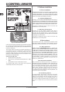
Example of the Learn function:
In order to control the main volume level of a virtual
instrument with the E19 slider, follow the steps below:
1. Press and hold the EDIT/EXIT push button.
2. Move the E19 slider.
3. Release the EDIT/EXIT push button.
4. Press the LEARN key.
5. Now move the volume control of the software
instrument with your computer’s mouse.
6. When “Gd!” appears on the display, press the ENTER
key.
7. To save these settings, store them in a preset.
5. UMA25S as USB/MIDI controller