


7
U-CONTROL UMX25
3. CONTROL ELEMENTS AND CONNECTIONS
What settings do I have to make? Where? How?
Basically, which control element generates which controller
must be set on the UMX25, and how incoming controller
commands should be interpreted must be set on the receiving
device.
Regarding controller assignment, there are two possible
principles:
V You use the preset controller configuration set in the
factory (see Fig. 3.1, ). In this case, you only need to
make the assignments on the receiving device.
V You use your own controller configuration set up in ASSIGN
mode. How to assign controllers to the UMX25 is described
in Chapter 4 “OPERATION”.
2.2 USB mode and stand-alone operation
The UMX25 can be operated as a USB interface or stand-
alone device. The two modes are different with respect to the
MIDI signal flow.
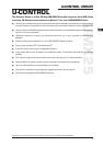
2.2.1 USB mode
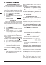
When the UMX25 is linked via USB to a computer, the signal
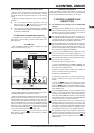
flow is as shown below (Fig. 2.1).
ON
OFF
Sound-Modul
POWERCOMBITYPEPROG
MUTE
DEMO
FILTER LEVEL
PLAY
PHONES
VOLUME
MIDI
(intern)
IN
OUT
USB
(intern)
Fig. 2.1: Block diagram of MIDI signal flow
After the UMX25 has been connected to the host computer, a
virtual MIDI IN and MIDI OUT interface is emulated.
MIDI data generated in the UMX25 are first sent over the USB
interface to the host computer, where they are received at the
emulated MIDI IN. A sequencer software running on the host
computer receives the MIDI data via the MIDI IN and relays them
to the emulated MIDI OUT—if all sequencer parameters are set
properly. The data are then sent back to the UMX25 via the USB
interfaces on the computer/UMX25, where they are looped
through to the physical MIDI OUT ( ). From here, the MIDI data
are sent to the devices connected to the MIDI OUT.
The MIDI OUT connector can also be used as a normal
MIDI interface, independently of the sequencer software
operating the UMX25.
2.2.2 Stand-alone operation
When the UMX25 is not linked via USB to a computer, it is
automatically set to stand-alone mode. In this case, the UMX25
can only send out MIDI data from its MIDI OUT connector.
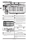
3. CONTROL ELEMENTS AND
CONNECTIONS
The following factory settings refer to GLOBAL MIDI
channel 1.
The keyboard of the UMX25: 25 large, velocity-sensitive
keys for maximum playing comfort. The keyboard not only
provides for playing, but also functions as an encoder in
the context of the assignment procedure.
The MODULATION wheel functions ex works as a
conventional modulation wheel (MIDI CC 1). In ASSIGN mode,
any MIDI controller can be assigned to it. When you release
the MODULATION wheel, it retains its adjusted value.
The PITCH BEND wheel is normally used to change the
pitch in real time. In this way, a sound can be “bent” upwards/
downwards by several semitones while playing. The
specific amount of pitch bending applied to a sound can be
set on the device controlled by the UMX25.
Ex works, the VOLUME/DATA fader controls the volume
of the notes played on the keyboard (MIDI CC 7). In
ASSIGN mode, it can be set to control any MIDI controller.
The ASSIGN button allows you to assign different functions
to the various control elements.
The basic principle is always the same:
1) Press the ASSIGN button and keep it pressed. The
status LED above the button lights up. The UMX25 signals
that it has entered ASSIGN mode.
2) Select the control element to which you would like to
assign a new MIDI function by operating it.
3) Release the ASSIGN button.
4) Depending on the choice you made, you may have to
define an additional value range (see below for more
details).
5) Press the button on the keyboard to confirm
your assignments. To discard your assignments either
press the button or the ASSIGN button again. In
either case, the ASSIGN LED goes out and the UMX25
quits ASSIGN mode.
The USER MEMORY button is used to recall the internal
memory. The internal memory contains all assignment
information set in ASSIGN mode. Any changes that were
made after USER MEMORY selection are automatically
saved without further user prompts. The USER MEMORY
is retained even after the unit is switched off.
The two OCTAVE SHIFT buttons are preset to shift the
keyboard range by several octaves up or down. The
associated LEDs help you identify the current octave setting
(see Table 3.1). Since the OCTAVE SHIFT buttons can also
be assigned to any MIDI controller, we would like to refer
you to Chapters 4.2.8 and 4.2.9 for detailed information.
The eight high-resolution rotary controls R1 – R8 generate
continuous controller information. They are the controllers
that are shown above the buttons in the table . All
rotary controllers can be assigned to any controller in
ASSIGN mode.