


ENGLISH
U-CONTROL UMX490/UMX610 User Manual
4
ENGLISH
U-CONTROL UMX490/UMX610 User Manual
5
Online registration1.3
Please remember to register your new BEHRINGER
equipment right after your purchase by visiting
www. behringer. com (alternatively www.behringer.de) and
read the terms and conditions of our warranty carefully.
Should your BEHRINGER product malfunction, our goal
is to have it repaired as quickly as possible. To arrange for
warranty service, please contact the retailer from whom the
equipment was purchased. Should your BEHRINGER dealer
not be located in your vicinity, you may directly contact
one of our subsidiaries. Corresponding contact information
is included in the original equipment packaging (Global
Contact Information/European Contact Information). Should
your country not be listed, please contact the distributor
nearest to you. A list of distributors can be found in the
support area of our website (www.behringer.com).
Registering your purchase and equipment with us helps us
process your repair claims quicker and more efficiently.
Thank you for your cooperation!
System requirements1.4
For USB operation, a current WINDOWS PC or MAC with
a USB connection is sufficient. Both USB 1.1 and USB 2.0
are supported.
The UMX supports the USB MIDI compatibility of
◊
WINDOWS XP, Vista and MAC OS X operating systems.
The UMX can also be operated as a stand-alone MIDI
◊
controller with no PC connected. Software control via
MIDI is also possible, provided your computer has a
MIDI interface.
Introduction to MIDI2.
MIDI control for beginners2.1
Application possibilities for the UMX models are truly wide-
ranging. We’ll start with a couple of general explanations
and examples that should quickly let you get a good
understanding of MIDI basics.
The definition of the MIDI standard began in 1982 with
the cooperation of various international companies
(MIDI: Musical Instrument Digital Interface). At that time,
musicians were looking for a possibility of managing
the communication of electronic musical instruments of
different makes with one another.
What exactly does the UMX do?
Simply put, this is a remote control for all kinds of MIDI
equipment. Using the faders, rotary knobs and buttons,
the foot pedal and the keyboard, an entire array of control
instructions can be generated, which in turn can control the
most diverse functions of external devices.
What kinds of equipment can I control with the UMX?
You can basically control any device supporting the MIDI
format. Both hardware and software MIDI devices are
controlled in exactly the same way. The only difference is in
the wiring. Here are a couple of suggestions on how you can
use your UMX:
Editing sound parameters of (virtual) synthesizers, sound •
samplers, GM/GS/XG sound generators
Controlling parameters on effects equipment/software •
plug-ins such as effects processors, reverbs, compressors,
equalizers
Remotely controlling software mixers (volume, •
panorama, mute functions, etc.) Remotely controlling
transport functions (playback, forward, stop, etc.) on
sequencers, hard disk recorders, drum computers,
etc. Live control of volume and sound parameters on
expanders
Remotely controlling groove boxes, step sequencers, •
MIDI generators and other “live” software
Program changes and volume control on sound •
generators (just like on a master keyboard)
Can be used by band keyboardists, solo entertainers, •
organists, electronic music performers, DJs, sound
engineers, home/project studio owners, theater
technicians, etc.
And how does it work?
Remote control is realized by assigning the individual
control elements of the UMX to individual MIDI parameters.
Whenever one of these control elements is operated, the
UMX generates the control data assigned to this control
element, which are then transferred to external devices
over a data link. Thus, for example, the VOLUME/DATA fader
is factory-set to send data controlling the volume level of
a channel.
The data connection is usually a standard MIDI cable with a
5-pin DIN plug on each end. Such cables should not exceed
a length of 15 meters. With the UMX there is one more data
connection available: the USB cable to the host computer.
Here, the cable should not exceed a length of 5 meters.
The data transmission takes place over 16 channels.
The control data generated by the individual control
elements are also called MIDI messages, which can be
divided into 3 major groups:
Channel Messages: • Here, channel-specific control
information is transmitted. An example of a channel
message is the note-on instruction. As soon as a key
is played on the keyboard of the UMX, the device
generates an instruction which contains the pitch,
channel number and velocity. The receiving sound
generator “knows” which tone has to be played.
System Messages:• These messages are not channel-
specific but relate to the entire system to which they are
sent. They are divided into 3 groups: System Exclusive
Messages (for operating system backup, updates,
management of memory contents); System Real-Time
Messages (e.g. for remote control of other devices);
System Common Messages (e.g. for the synchronization
of several devices).
Control Messages:• Also known as Control Changes
or Controllers, abbreviated as “CC… (Control Change)”.
There are 128 controllers in total, which are numbered
from 0 to 127.
Please refer to Table 6.1 to find out which type of
◊
controller you are currently working with.
MIDI data are only control data and contain no audible
◊
audio information! The data transmission takes place over
16 channels.
What settings do I have to make? Where? How?
Basically, which control element generates which controller
must be set on the UMX, and how incoming controller
commands should be interpreted must be set on the
receiving device. Regarding controller assignment, there are
two possible principles:
You use the preset controller configuration set in the •
factory (see Fig. 3.1). In this case, you only need to make
the assignments on the receiving device.
You use your own controller configuration set up in •
ASSIGN mode. How to assign controllers to the UMX is
described in Chapter 4 “Operation”.
USB mode and stand-alone 2.2
operation
The UMX can be operated as a USB interface or stand-alone
device. The two modes are different with respect to the MIDI
signal flow.
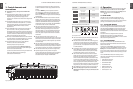
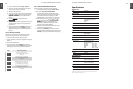
USB mode2.2.1
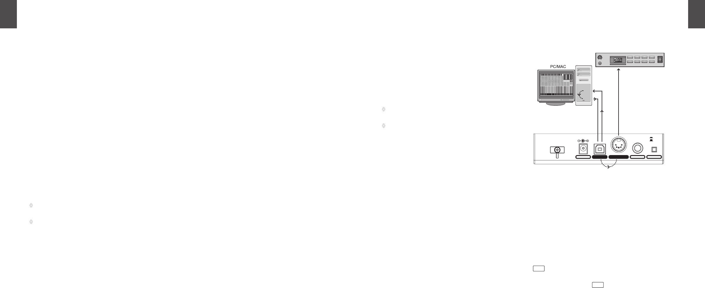
When the UMX is linked via USB to a computer, the signal
flow is as shown below (Fig. 2.1).
Fig 2.1: Block diagram of MIDI signal flow
After the UMX has been connected to the host computer, a
virtual MIDI IN and MIDI OUT interface is emulated.
MIDI data generated in the UMX are first sent over the USB
interface to the host computer, where they are received at
the emulated MIDI IN. A sequencer software running on the
host computer receives the MIDI data via the MIDI IN and
relays them to the emulated MIDI OUT—if all sequencer
parameters are set properly. The data are then sent back
to the UMX via the USB interfaces on the computer/UMX,
where they are looped through to the physical MIDI OUT
14
. From here, the MIDI data are sent to the devices
connected to the MIDI OUT.
The MIDI OUT connector
14
can also be used as a normal
MIDI interface, independently of the sequencer software
operating the UMX.
Stand-alone operation2.2.2
When the UMX is not linked via USB to a computer, it is
automatically set to stand-alone mode. In this case, the UMX
can only send out MIDI data from its MIDI OUT connector.
ON
OFF
Sound-Module
POWERCOMBITYPEPROG
MUTE DEMO FILTER LEVEL
PLAY
PHONES
VOLUME
MIDI
(intern)
IN
OUT
USB
(intern)