


POWERMATE
3
15
Using RCA plugs
The RCA inputs CD 1-2 and CD 3-4 are connected in parallel to the phone inputs. Do not connect signal sources to phone
and RCA inputs at the same time.
Using the DIGITAL AUDIO INTERFACE (USB)
When using the DIGITAL AUDIO INTERFACE two stereo signals are available at USB 1-2 or USB 3-4. Do not connect signal
sources to phone inputs when using the DIGITAL AUDIO INTERFACE for playback. See page 21 for more details about
the DIGITAL AUDIO INTERFACE.
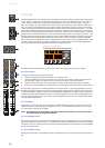
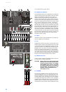
18 - GAIN MIC
Rotary controls for adjusting the MIC inputs’ sensitivity, providing the possibility to optimally match the incoming signals
with the mixer’s internal operation level. The GAIN MIC control in the stereo channel is only active for the XLR-type input.
For further information about setting and functioning of these controls, please refer to the chapter “GAIN” of the MONO
INPUT description within this manual.
CAUTION: The GAIN MIC control of an inactive microphone input should always be set to its minimum position.
Otherwise the noise of the inactive input is added to the audio signal of the corresponding LINE input,
which could lead to unnecessary extra noise at the master output, becoming clearly intelligible in pro-
gram breaks.
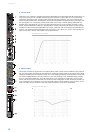
19 - GAIN LINE CD / USB
These rotary controls are for matching the incoming line level signals to the operating level of the PowerMate. The total
adjustment range is 30 dB. Unity gain – no amplification (0 dB) – is achieved at the 0 dB mark. The control offers level
reduction of -10 dB and an amplification of +20 dB. This range allows the connection of most professional, semi profes-
sional, and hi-fi sound sources. For further details on how to set the LINE TRIM control, please refer to the description
of the GAIN control in monaural channels.
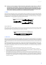
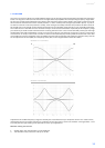
Illustration 2-11: Unbalanced or balanced assignment of phone plus
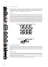
Illustration 2-12: RCA inputs CD 1-2 and 3-4
Input PowerMate 1000 PowerMate 1600 PowerMate 2200
CD 1-2 Stereo 7-8 Stereo 13-14
CD 3-4 Stereo 9-10 Stereo 15-16
Table 2-13: Assignment of CD 1-2 or CD 3-4 inputs to PowerMate input channels
Illustration 2-14: DIGITAL AUDIO INTERFACE
Input PowerMate 1000 PowerMate 1600 PowerMate 2200
USB 1-2 Stereo 11-12 Stereo 17-18
USB 3-4 Stereo 13-14 Stereo 19-20
Table 2-15: Assignment of USB 1-2 or USB 3-4 inputs to PowerMate input channels
UNBALANCED
SHIELD
HOT
BALANCED
SHIELD COLD
HOT