


POWERMATE
3
22
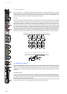
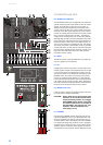
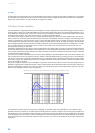
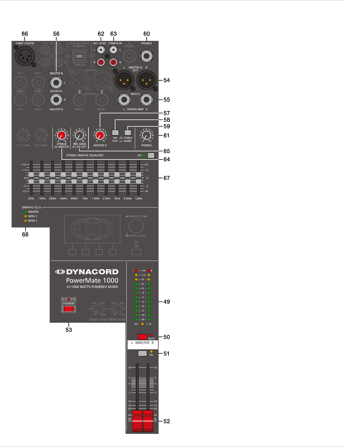
2.6 MASTER with GEQ
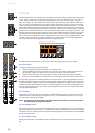
49 - MASTER LED-DISPLAY
The PowerMate offers two 12-segment LED-chains for
optical monitoring the output levels of the L/R master
signals. The indication range of the LED-meter is
40 dB, indicating the levels that are present at the
master outputs in dBu. The meter’s 0 dB mark is ref-
erenced to a 0 dBu output signal at the mixer output.
Further increasing the level leads to the power ampli-
fier’s maximum input level of +8 dBu – equaling an
output power of 1000 watts into 4 ohms per channel.
Although higher levels are being displayed, the power
amp’s clip limiter already limits the signal, which is in-
dicated by the lit LIMIT LED in the status display. As
soon as a PFL button is engaged, the PFL LED lights.
The meter instrument in the master section is simulta-
neously switched, so that the left LED-chain indicates
the level of the actually chosen channel (in dBu). The
right LED-chain indicates the level of the summed
post-fader master output.
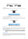
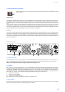
50 - MUTE
The MUTE button mutes the MASTER L/R output sig-
nal. PFL signals are not affected.
51 - PFL
Engaging the master PFL-button, the pre fader mono
master signal is routed to the headphones bus, so that
it can be monitored via headphones output. The vol-
ume of this signal is not affected by the setting of the
MASTER fader. The meter instrument in the master
section is simultaneously switched, so that the left
LED-chain indicates the level of the summed pre-fader
L/R master signal channel (in dBu), which basically is
the master bus level, while the right LED indicates the
level of the summed post-fader master output.
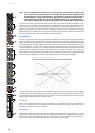
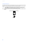
52 - MASTER L/R
FADER
Level controls to adjust the output signals of the left
and right master outputs (MASTER).
CAUTION: Please, make sure to set the input chan-
nel faders or at least the master faders
to their minimum position, or to engage
the STANDBY switch, before connecting
an external sound source to an input of
the PowerMate. This will save you, your
audience, and the equipment from
unnecessary stress.
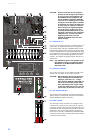
53 - STANDBY
Pressing the STANDBY switch mutes the output sig-
nals at the MASTER A OUT L/R, MASTER B OUT L/R,
AUX 1/2 and MON 1/2 outputs. The outputs FX 1/2
and REC SEND L/R are still operational. The STANDBY
LED lights indicating that stand-by mode is engaged
and that input channel signals are not output via the
speaker systems. However, audio signals connected
via 2TRACK IN or the DIGITAL AUDIO INTERFACE (see