


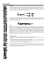
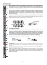
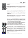
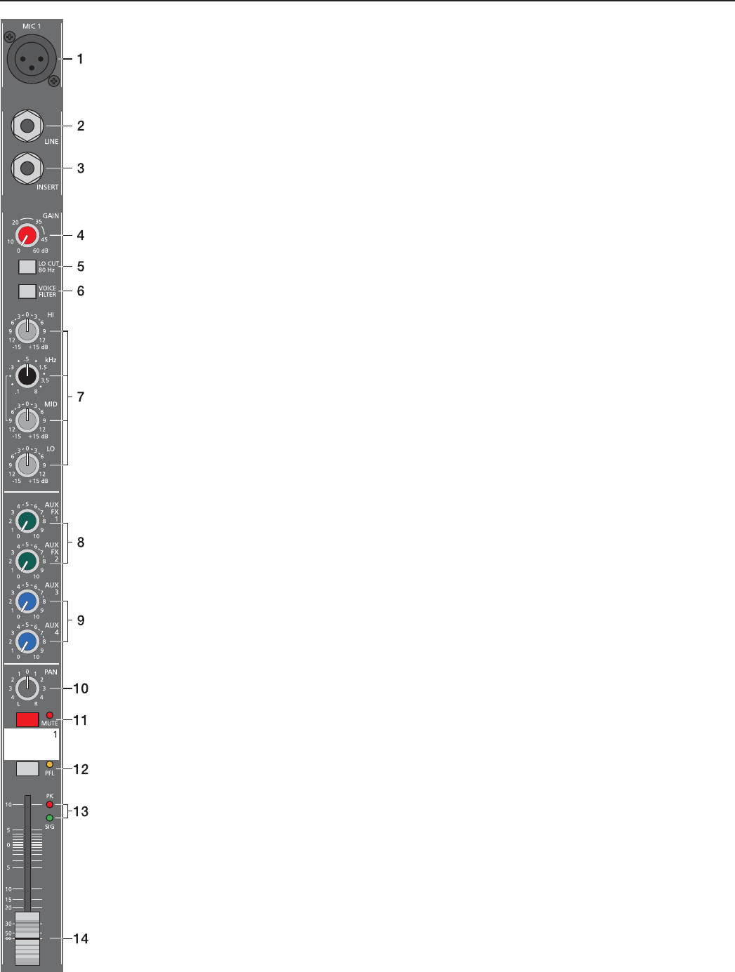
10. PAN
This control determines the position of the connected sound source within the stereo image. When the control is
set at its center position, the audio signal is fed with equal levels to the L and R master busses. The PAN control
section is designed to maintain the essential sound pressure level, no matter at what position within the stereo
image the PAN control is set to.
11. MUTE
The MUTE button mutes the input signal post fader, including all AUX sends. PFL and Signal/Peak stay
functional.
12. PFL
Engaging the PFL button routes the audio signal to the headphones bus, so that it is present at the phones
output connector. The meter instrument in the master section is simultaneously switched, so that the left LED-
chain indicates the level (in dBu) of the actually chosen channel, which allows optimally matching the level of
the signal source. The phones output volume does not dependent on the setting of the corresponding channel
fader (PRE FADER LISTEN), which provides the possibility to listen to or shape the sound of the selected audio
signal, without need to include it in the main mix.
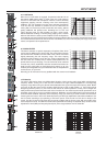
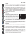
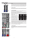
13. SIGNAL / PEAK Indicator
The signal-peak indicator plays a key role when setting input levels. The PK (peak) LED of the CMS provides
optical indication of the risk of occurring overdrive before you would actually hear the distortion over the
connected speaker systems. As outlined in the setting instructions, the Signal-LED should blink in the rhythm of
the incoming signal. If this is not the case, you have to increase the gain. If, on the other hand, the PEAK LED
blinks frequently or lights continuously, the corresponding channel is likely to enter clipping and you have to
turn the gain control a bit to the left. The signal LED lights at –30dB and the peak LED lights at a level of –6dB
below clipping. Keeping an eye on the indicator during a performance is also a good idea, because some very
dynamically performing members of a band or changing keyboard setups can easily lead to channel clipping,
resulting in the degradation of the overall sound.
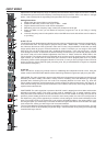
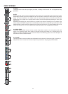
14. VOLUME
The channel faders set the volume of the corresponding channels, establishing an accurately proportioned
mix. The channel faders should be positioned within the range of –5dB to 0dB, leaving you with a degree of
control that allows the precise matching of relative big differences in the input levels of different channels. The
overall volume is set through the use of the master faders. Even though the channel faders offer an additional
amplifi cation of +10dB, we would like to advise you to exceed the +5dB mark only in very few exceptional
cases. If the mixer’s summing bus gets overloaded with too many high level input channels, despite its special
gain structure, the summing amplifi er could be driven into clipping. Lowering the setting of each channel fader
by about –5dB and increasing the overall output level by elevating the master faders is the wiser solution. The
proportion of the mix and the overall volume stay the same while the risk of clipping is banished.
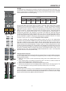
INPUT MONO
9