


0150-0198H 11 DVMRe Triplex eZ
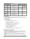
Pin 1: Alarm Input 1.
Pin 2: Alarm Input 2.
Pin 3: Alarm Input 3.
Pin 4: Alarm Input 4.
Pin 5: Alarm Input 5.
Pin 6: Alarm Input 6.
Pin 7: Alarm Input 7.
Pin 8: Alarm Input 8.
Pin 9: Alarm Input 9.
Pin 10: Alarm Input 10.
Pin 11: Alarm Input 11.
Pin 12: Alarm Input 12.
Pin 13: Alarm Input 13.
Pin 14: Alarm Input 14.
Pin 15: Alarm Input 15.
Pin 16: Alarm Input 16.
Pin 17: Alarm Output Relay #1.
Pin 18: Ground.
Pin 19: Ground.
Pin 20: Ground.
Pin 21: Alarm Output Relay #1 Common.
Pin 22: Alarm Output Relay #2.
Pin 23: External Alarm Silence and Acknowledge Input.
Pin 25: Alarm Output Relay #2 Common.
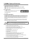
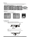
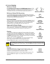
NO1A1 A2A14 A15 A16A3 A4 A5 GND
A
7
GNDA6
NO2 COM1
G
N
D
A8A9A10 GNDACKA11VextA12A13COM2
171 214 15 163 4 5 18 7196
Signal
PIN
22 21 208910 202311241213 25
Signal
PIN
Alarm PCB
Active alarm inputs vary by DVMRe model. 4 channel units (4eZT) have 4 active alarm inputs. 10
channel units (10eZT) have 10 active alarm inputs.
Alarm Input
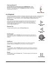
An alarm condition can be activated by devices such as pressure pads, passive infrared detectors,
door switches, or other similar devices.
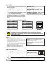
Alarm Relay Output
Output: Normally Open Zero
potential relay contact.
Voltage: 30V (Max)
Current: 500mA (Max)
The alarm relay output is activated when an alarm condition
exists. The alarm output is only active for the duration of the
alarm.
Alarm relays can be programmed in the menu system to
respond to macros, and video loss. See section 3.11 for
information about configuring the alarms in the menu system.
External Alarm Acknowledge Input
External Device: Normally Open
Zero potential relay contact.
Connect a switch or similar device to ground this pin in order
to acknowledge an alarm condition, and silence associated
buzzers and relays. Connect from pin 23 to either pin 18, 19,
or 20 (ground pins).
All specifications subject to change without notice. GE-Security believes all specifications
to be correct at time of printing, but no liability is assumed for omissions or errors.
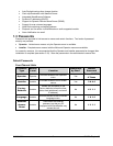
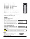
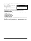
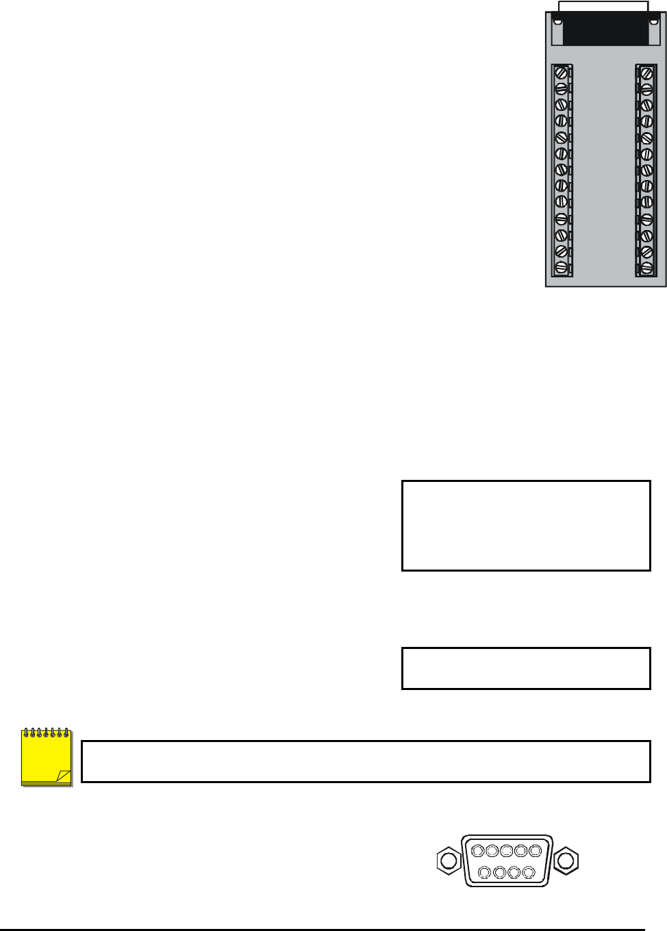
AUX Port
The back panel of the unit is equipped with an Aux Port
(DB-9 style connector).
Do not attempt to wire directly to the DB-9
connector on the back panel.
1
5
6
9
DB-9 Connector on Back Panel
NOTE