


0150-0198H 56 DVMRe Triplex eZ
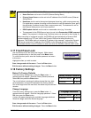
4 Alarms
4.1 Alarm Input
Alarm devices are connected via the Alarm PCB on the back panel of the unit (see section 1.7). Each
Alarm Input corresponds with the Camera Input of the same number. Alarm input to camera number
assignments can be changed on 10 and 16-channel models. See Alarm Action menu (section 3.10).
4.2 Alarm Output
Front Panel Alarm LED: The LED located to the left and above the Alarm button is lit for the duration
of the alarm.
Internal Buzzer: The internal buzzer is activated until it is Silenced and Acknowledged. This feature
can be turned off in the menu system (see Buzzer Setup in section 3.10).
Monitor Displays: Discussed below in the On-screen Displays During Alarms section.
Output Relays: The alarm output relay is active for the duration of the alarm.
Macro Activation: Unit can be configured in the menu system to activate a macro when an alarm is
detected (see Link to Macro in section 3.10).
Record Rate: Record Rate can be increased by recording at the Alarm Record Rate (see section
3.10) and by Interleaved or Exclusive Recording (see Alarm Record mode in section 3.10).
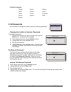
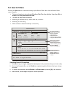
4.3 Alarm Acknowledge
Pressing the Alarm button acknowledges to the unit that the alarm has been
recognized and silences the internal buzzer. This does not clear the alarm
condition.
Alarm Button
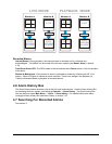
4.4 On-screen Displays During Alarms
Monitor-A and Monitor-B Display During Alarm
Single Alarm: Unit switches to a full screen display of the camera in alarm.
Additional Alarms: Unit switches to a sequenced display of all cameras in alarm.
4.5 Alarm Operations During Playback
Live Alarms Displays
Single Alarm: Unit switches to a full screen display of the camera in alarm on Monitor B.
Additional Alarms: Unit switches to a sequenced display of all cameras in alarm on Monitor B.