


0150-0198H 12 DVMRe Triplex eZ
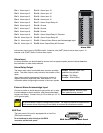
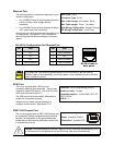
Connect the Accessory PCB (supplied with the audio equipped models) to the AUX port to access the
Audio features. Wire the audio input and output to the Accessory PCB per the pin out specifications
shown below.
Pin 1: Not Used.
Pin 2: Audio Out.
Pin 3: Ground.
Pin 4: Audio In.
Pin 5: Ground.
Pin 6: Not Used.
Pin 7: Ground.
Pin 8: Not Used.
Pin 9: Ground.
GND: Ground.
1
2
3
4
5
6
7
8
9
GND
Accessory PCB
Warning! The use of clandestine listening and recording devices is forbidden by
Federal Law as well as other State and Municipal Jurisdictions. Please review local and
Federal Law prior to the installation or operation of this equipment to ensure that you
are in legal compliance with the Authorities having Jurisdiction.
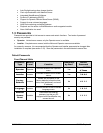
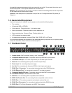
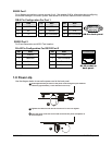
RS485 Connector
Wire Type:
#24 AWG, twisted pair with shield
(2-wire)
Connector Type: RJ-45
Max. Cable Length: 3200 feet / 1000 meters
Shields are grounded at one end, preferably at the
DVMRe
Triplex eZ.
See section 3.16 for information about configuring
the RS485 network address settings in the menu
system.
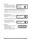
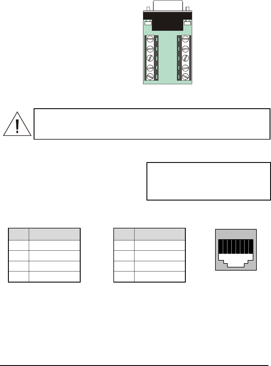
RJ-45 Pin Configuration For RS485 Port
Pin Use
Pin Use
1 Ground (Shield) 5 Not Connected
2 Not Connected 6 Network -VE
3 Network +VE 7 Ground (Shield)
4 Not Connected 8 Not Connected
82 3 4 5 6 71
RJ-45 socket on
back panel.