


DIAGNOSTIC STATUS CODES
SX TRANSISTOR CONTROL Page 16
January 2000
Section 4.0 TROUBLESHOOTING AND DIAGNOSTIC STATUS CODES
Section 4.1 General Maintenance Instructions
The transistor control, like all electrical apparatus, does
have some thermal losses. The semiconductor junctions
have finite temperature limits, above which these devices
may be damaged. For these reasons, normal maintenance
should guard against any action which will expose the
components to excessive heat and/or those conditions
which will reduce the heat dissipating ability of the control,
such as restricting air flow.
The following Do’s and Don’t’s should be observed:
Any controls that will be applied in ambient temperatures
over 100° F (40° C) should be brought to the attention of the
vehicle manufacturer.
All external components having inductive coils must be
filtered. Refer to vehicle manufacturer for specifications.
The wiring should not be directly steam cleaned.
In dusty
areas, blow low-pressure air over the control to remove
dust. In oily or greasy areas, a mild solution of detergent or
denatured alcohol can be used to wash the control, and
then low-pressure air should be used to completely dry the
control.
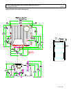
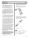
For the control to be most effective, it must be mounted
against the frame of the vehicle. The metal vehicle frame,
acting as an additional heat sink, will give improved vehicle
performance by keeping the control package cooler. Apply
a thin layer of heat-transfer grease (such as Dow Corning
340) between the control heat sink and the vehicle frame.
Control wire plugs and other exposed transistor control
parts should be kept free of dirt and paint that might
change the effective resistance between points.
CAUTION: The vehicle should not be plugged when the
vehicle is jacked up and the drive wheels are in a free
wheeling position. The higher motor speeds can create
excessive voltages that can be harmful to the control.
Do not hipot (or megger) the control. Refer to control
manufacturer before hipotting.
Use a lead-acid battery with the voltage and ampere hour
rating specified for the vehicle. Follow normal battery
maintenance procedures, recharging before 80 percent
discharged with periodic equalizing charges.
Visual inspection of GE contactors contained in the traction
and pump systems is recommended to occur during every
160 hours of vehicle operation. Inspection is recommended
to verify that the contactors are not binding and that the
tips are intact and free of contaminants.
GE does not recommend that any type of welding be
performed on the vehicle after the installation of the
control(s) in the vehicle. GE will not honor control failures
during the warranty period when such failures are
attributed to welding while the control is installed in the
vehicle.
Section 4.2 Cable Routing and Separation
Electrical noise from cabling of various voltage levels can
interfere with a microprocessor-based control system. To
reduce this interference, GE recommends specific cable
separation and routing practices, consistent with industry
standards.
Section 4.2.1 Application Responsibility
The customer and customer’s representative are
responsible for the mechanical and environmental
locations of cables. They are also responsible for applying
the level rules and cabling practices defined in this section.
To help ensure a lower cost, noise-free installation, GE
recommends early planning of cable routing that complies
with these level separation rules.
On new installations, sufficient space should be allowed to
efficiently arrange mechanical and electrical equipment.
On vehicle retrofits, level rules should be considered during
the planning stages to help ensure correct application and
a more trouble-free installation.
Section 4.2.2. Signal/Power Level Definitions
The signal/power carrying cables are categorized into four
defining levels: low, high, medium power, and high power.
Within those levels, signals can be further divided into
classes.
Sections 4.2.2.a through 4.2.2.d define these levels and
classes, with specific examples of each. Section 4.2.3
contains recommendations for separating the levels.
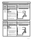
4.2.2.a Low-Level Signals (Level L)
Low-level signals are designated as level L. These consist
of:
•= Analog signals 0 through ±15 V
•= Digital signals whose logic levels are less than 15 V DC
•= 4 – 20 mA current loops
•= DC busses less than 15 V and 250 mA
The following are specific examples of level L signals used
in drive equipment cabling: