


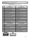

DIAGNOSTIC STATUS CODES
SX TRANSISTOR CONTROL Page 17
January 2000
•= Control common tie
•= DC buses feeding sensitive analog or digital hardware
•= All wiring connected to components associated with
sensitive analog hardware with less than 5V signals (for
example, potentiometers and tachometers)
•= Digital tachometers and resolvers
•= Dash display cabling
•= RS-232 cabling
Note: Signal inputs to analog and digital blocks should be
run as shielded twisted-pair (for example, inputs from
tachometers, potentiometers, and dash displays).
4.2.2.b High-Level Signals (Level H)
High-level signals are designated as level H. These signals
consist of:
•= Analog and digital signals greater than 15 V DC and
less than 250 mA
For example, switch inputs connected to battery volts are
examples of level H signals used in drive equipment
cabling.
4.2.2.c Medium-Power Signals (Level MP)
Medium power signals are designated as level MP. These
signals consist of:
•= DC switching signals greater than 15 V
•= Signals with currents greater than 250 mA and less than
10A
The following are specific examples of level MP signals
used in drive equipment cabling:
•= DC busses less than 10 A
•= Contactor coils less than 10 A
•= Machine fields less than 10 A
4.2.2.d. High Power Signals (Level HP)
Power wiring is designated as level HP. This consists of DC
buses and motor wiring with currents greater than 10 A.
The following are specific examples of level HP signals
used in drive equipment cabling:
•= Motor armature loops
•= DC outputs 10 A and above
•= Motor field loops 10 A and above
4.2.3. Cable Spacing Guidelines
Recommended spacing (or clearance) between cables (or
wires) is dependent on the level of the wiring inside them.
For correct level separation when installing cable, the
customer must apply the general guidelines (section
4.2.3.a), outlined below.
4.2.3.a General Cable Spacing
The following general practices should be used for all
levels of cabling:
•= All cables and wires of like signal levels and power
levels must be grouped together.
•= In general, different levels must run in separate wire
bundles, as defined in the different classes, identified
above. Intermixing cannot be allowed, unless noted by
exception.
•= Interconnecting wire runs should carry a level
designation.
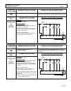
•= If wires are the same level and same type signal, group
those wires from one location to any other location
together in multiconductor cables or bind them
together with twine or zip-ties.
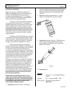
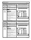
•= When unlike signals must cross, cross them in 90°
angles at a maximum spacing. Where it is not possible
to maintain spacing, place a grounded steel barrier
between unlike levels at the crossover point.
4.2.4 Cabling for Vehicle Retrofits
Reducing electrical noise on vehicle retrofits requires
careful planning. Lower and higher levels should never
encircle each other or run parallel for long distances.
It is practical to use existing wire runs or trays as long as
the level spacing (see section 4.2.2) can be maintained for
the full length of the run.
Existing cables are generally of high voltage potential and
noise producing. Therefore, route levels L and H in a path
separate from existing cables, whenever possible.
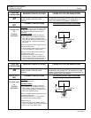
For level L wiring, use barriers in existing wire runs to
minimize noise potential.
Do not loop level L signal wires around level H, level MP, or
HP wires.
4.2.5 RF Interference
To prevent radio frequency (RF) interference, care should
be taken in routing power cables in the vicinity of radio-
controlled devices.
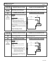
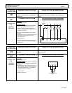
Section 4.2.6 Suppression
Unless specifically noted otherwise, suppression (for
example, a snubber) is required on all inductive devices
controlled by an output. This suppression minimizes noise
and prevents damage caused by electrical surges.