


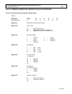
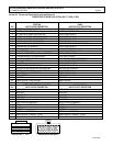
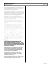
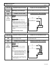
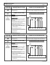
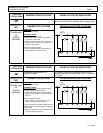

DIAGNOSTIC STATUS CODES
SX TRANSISTOR CONTROL Page 19
January 2000
Section 4.4 General Troubleshooting Instructions
Trouble-shooting the SX family of controls should be quick
and easy when following the instructions outlined in the
following status code instruction sheets.
If mis-operation of the vehicle occurs, a status code will be
displayed on the Dash Display (for vehicles equipped with a
Dash Display) or made available by plugging a Handset into
the plug "Y" location, and then reading the status code.
Note: Status code numbers from 00 to 99 are traction
control status codes. Status codes with the prefix 1 (101 to
199) are pump control status codes.
With the status code number, follow the procedures
outlined in the status code instruction sheets to determine
the problem.
Important Note: Due to the interaction of the logic card
with all vehicle functions, almost any status code or
control fault could be caused by the logic card. After all
other status code procedures have been followed and no
problem is found, the controller should then be replaced as
the last option to correct the problem.
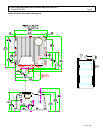
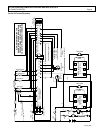
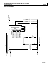
The same device designations have been maintained on
different controls but the wire numbers may vary. Refer to
the elementary and wiring diagrams for your specific
control. The wire numbers shown on the elementary
diagram will have identical numbers on the corresponding
wiring diagrams for a specific vehicle, but these numbers
may be different from the numbers referenced in this
publication.
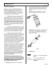
WARNING: Before trouble-shooting, jack up the drive
wheels, disconnect the battery and discharge the
capacitors. Reconnect the battery as needed for specific
checks. Capacitors should be discharged by connecting a
200 ohm 2 watt resistor between the positive and negative
terminals on the control panel.
Check resistance on R x 1000 scale from frame to power
and control terminals. A resistance of less than 20,000
ohms can cause misleading symptoms. Resistance less
than 1000 ohms should be corrected first.
Before proceeding, visually check for loose wiring,
mis-aligned linkage to the accelerator switch, signs of
overheating of components, etc.
Tools and test equipment required are: clip leads, volt-ohm
meter (20,000 ohms per volt) and basic hand tools.