


INSTALLATION AND OPERATION
SX TRANSISTOR CONTROL Page 2
January 2000
2.1.3.d Auto Braking.............................................................................................................. 6
2.1.4 Auxiliary Speed Control.................................................................................................... 6
2.1.4.a Field Weakening................................................................................................................ 6
2.1.4.b Speed Limits ...................................................................................................................... 7
2.1.4.c Proportional Operation for Dual Motor Vehicles.......................................................... 7
2.1.5 Ramp Operation ................................................................................................................ 7
2.1.5.a Ramp Start ................................................................................................................. 7
2.1.5.b Anti-Rollback............................................................................................................. 7
2.1.6 Steer Pump Contactor Time Delay ................................................................................. 7
2.1.7 On-Board Coil Drivers and Internal Coil Suppression ................................................. 8
2.2 System Protective Override ..................................................................................................... 8
2.2.1 Static Return to Off (SRO) ............................................................................................... 8
2.2.2 Accelerator Volts Hold Off............................................................................................... 8
2.2.3 Pulse Monitor Trip (PMT)................................................................................................. 8
2.2.4 Thermal Protector (TP)..................................................................................................... 8
2.2.5 Low Voltage ...................................................................................................................... 8
2.3 Diagnostics................................................................................................................................ 8
2.3.1 Systems Diagnostics...................................... .................................................................. 8
2.3.2 Status Codes...................................................................................................................... 8
2.3.2.a Standard Status Codes............................................................................................. 8
2.3.2.b Stored Status Codes ................................................................................................ 8
2.3.3 Hourmeter Readings ........................................................................................................ 9
2.3.3.a Maintenance Alert and Speed Limit .................... .................................................. 9
2.3.4 Battery Discharge Indication (BDI)....................... .........................................................9
2.3.4.a Internal Resistance Compensation ................................................................................ 9
2.3.5 Handset ............................................................................................................................. 9
2.3.6 RS-232 Communication Port ........................................................................................... 9
2.3.6.a Dash Display Interaction Modes ................... ............................................................... 9
2.3.7 Circuit Board Coil Driver Modules.................................................................................. 9
2.3.8 Truck Management Module (TMM) ............................................................................... 9
2.4 Hydraulic Pump Control........................................................................................................... 9
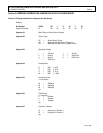
Section 3.0 ORDERING INFORMATION, ELEMENTARY AND OUTLINE DRAWINGS......................................................11
3.1 Ordering Information for Separately Excited Controls................................................................. 11
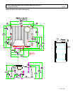
3.2 Outline: SX-3 and SR-3 Package Size............................................................................................. 12
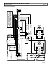
3.3 Traction Elementary ......................................................................................................................... 13
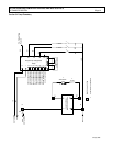
3.4 Pump Elementary.............................................................................................................................. 14
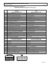
3.5 Traction and Pump Control Input / Output List ............................................................................. 15
Section 4.0 TROUBLESHOOTING AND DIAGNOSTIC STATUS CODES..............................................................................16
4.1 General Maintenance Instructions................................................................................................. 16
4.2 Cable Routing and Separation ............................................................................................... 16
4.2.1 Application Responsibility ............................................................................................... 16
4.2.2 Signal/Power Level Definitions ............................................................................................... 16
4.2.2.a Low Level Signals (Level L).............................................................................................. 16
4.2.2.b High Level Signals (Level H)............................................................................................. 17
4.2.2.c Medium-Power Signals (Level MP)................................................................................ 17
4.2.2.d High-Power Signals (Level HP) ....................................................................................... 17
4.2.3 Cable Spacing Guidelines........................................................................................................ 17
4.2.3.a General Cable Spacing..................................................................................................... 17
4.2.4 Cabling for Vehicle Retrofits.................................................................................................... 17
Table of Contents ( Continued )