


BASIC OPERATION AND FEATURES
SX TRANSISTOR CONTROL Page 5
January 2000
following description provides a brief introduction to
examples of some of these features.
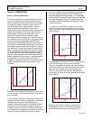
Section 1. 2 Solid-State Reversing
The direction of armature rotation on a shunt motor is
determined by the direction in which current flows through
the field windings. Because of the of the shunt motor field
only typically requires about 10% of the armature current at
full torque, it is normally cost effective to replace the
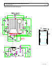
double-pole, double-throw reversing contactor with a low
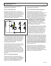
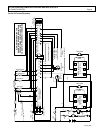
power transistor H-Bridge circuit (Figure 4).
By energizing the transistors in pairs, current can be made
to flow in either direction in the field. The armature control
circuit typically operates at 12KHZ to 15KHZ, a frequency
range normally above human hearing. This high frequency
coupled with the elimination of directional contactors,
provides very quiet vehicle operation. The field control
circuits typically operate at 2 KHZ.
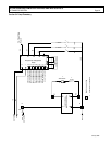
The line contactor is normally the only contactor required
for the shunt motor traction circuit. This contactor is used
for both pre-charge of the line capacitors and for
emergency shut down of the motor circuit, in case of
problems that would cause a full motor torque condition.
The line can be energized and de-energized by the various
logic combinations of the vehicle, i.e. activate on key, seat
or start switch closure, and de-energize on time out of idle
vehicle. Again, these options add to the quiet operation of
the vehicle.
Section 1. 3 Flexible System Application
Because the shunt motor controller has the ability to
control both the armature and field circuits independently,
the system can normally be adjusted for maximum system
efficiencies at certain operating parameters. Generally
speaking, with the ability of independent field and
armature, the motor performance curve can be maximized
through proper control application.
Section 1. 4 More Features with Fewer Components
Field weakening with a series wound motor is
accomplished by placing a resistor in parallel with the field
winding of the motor. Bypassing some of the current
flowing in the field into the resistor causes the field current
to be less, or weakened. With the field weakened, the motor
speed will increase, giving the effect of “overdrive”. To
change the “overdrive speed”, it is necessary to change
the resistor value. In a separately excited motor,
independent control of the field current provides for
infinite adjustments of “overdrive” levels, between
motor base speed and maximum weak field. The
desirability of this feature is enhanced by the
elimination of the contactor and resistor required for
field weakening with a series motor.
With a separately excited motor, overhauling speed
limit, or downhill speed, will also be more constant. By
its nature, the shunt motor will try to maintain a
constant speed downhill. This characteristic can be
enhanced by increasing the field strength with the
control. Overhauling load control works in just the
opposite way of field weakening, armature rotation
slows with the increase of current in the field.
Regenerative braking (braking energy returned to the
battery) may be accomplished completely with solid-state
technology. The main advantage of regenerative braking is
increased motor life. Motor current is reduced by 50% or
more during braking while maintaining the same braking
torque as electrical braking with a diode clamp around the
armature. The lower current translates into longer brush
life and reduced motor heating. Solid state regenerative
braking also eliminates a power diode, current sensor and
contactor from the circuit.
For GE, the future is now as we make available a new
generation of electric traction motor systems for electric
vehicles having separately excited DC shunt motors and
controls. Features that were once thought to be only
available on future AC or brushless DC technology vehicles
systems are now achievable and affordable.
FUSE
LINE
CAP
ARM
F2F1
Q3
Q4
Q5
Q6
Q1
POS
NEG
Figure 4
A1 +
A2 -
Q2