


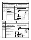
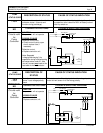
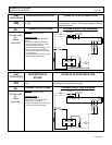
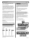

ADJUSTABLE FEATURES
SX TRANSISTOR CONTROLS Page 58
January 2000
FUNCTION 6 FW RATIO
(Push 6)
This function sets the ratio between armature and field
current when operating below the Field Weakening Start
point. The setting represents the quantity of field current
changed for each 1 amp of armature current changed.
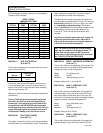
Max Fld Ref Set Resolution Per Unit Value
40 0 to 10 0.029 amps
The ratio value (VAL) is the set value divided by 10 and
rounded to the whole number.
Example: Setting of 45 = 45/10 = 4.5 = 4 VAL
I
FIELD
= VAL (I
MOTOR
x 0.029)
FUNCTION 7 MIN FIELD CURRENT
( Push 7 )
This function allows the adjustment of the field weakening
level in order to set the top speed of the motor.
Min Max Set Resolution Per Unit Value
0 40 51 to 255 0.185
MIN I
F
= (VAL-51) X 0.185
Important Note: This function is used to optimize motor
and control performance, and this setting will be
determined by GE and OEM engineers at the time of
vehicle development. This setting must not be changed by
field personnel without the permission of the OEM.
FUNCTION 8 MAX FIELD CURRENT
( Push 8 )
This function allows for the adjustment of the maximum
field current in order to obtain the maximum torque of the
motor.
Min Max Set Resolution Per Unit Value
0 40 51 to 255 0.185
MAX I
F
= (VAL-51) X 0.185
Important Note: This function is used to optimize motor
and control performance, and this setting will be
determined by GE and OEM engineers at the time of
vehicle development. This setting must not be changed by
field personnel without the permission of the OEM.
FUNCTION 9 REGEN BRAKING C/L
(Push 9)
This function allows for the adjustment of the Regen
braking current limit. High current correlates to shorter
stopping distance.
Resolution Example
Min Max Set Per unit value If set at 20
52A 468A 0 to 255 1.63 amps 84.6 amps
REGEN BRAKE I
A
= (VAL X 1.63) + 52
FUNCTION 10 FIELD CURRENT FOR REGEN
( Push 10 )
This function allows for the adjustment of the field current
to be used during the regen braking mode.
Resolution Example
Min Max Set Per unit value If set at 71
0 40 51 to 255 0.185 amps 3.7 amps
I
F
= (VAL-51) X 0.185
Important Note: This function is used to optimize motor
and control performance and this setting will be
determined by GE and OEM engineers at the time of
vehicle development. This setting must not be changed by
field personnel without the permission of the OEM.
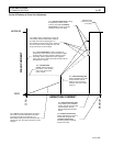
FUNCTION 11 TURN SPEED LIMIT
(Push 11)
This function allows for the adjustment of the speed limit
(maximum battery volts to the motor) when the SL1 signal is
calculated from the turn angle potentiometer by the control
card.
Range 100% to 0% battery volts
Set 51 to 180
Resolution 0.78% per set unit
Example Setting of 71 = 84.4% of battery volts
Note: To disable speed limit, and assure no 1A hold off, set
this function to a value of zero.
FUNCTION 12 MAX ARMATURE PERCENT ON
( Push 12 )
Same as function 11, this function allows for the
adjustment of the motor speed limit (maximum battery volts
to the motor). The dash display mode selection enables the
speed limit as well as setting the level of speed limit.