


BASIC OPERATION AND FEATURES
SX TRANSISTOR CONTROL Page 6
January 2000
Section 2. FEATURES OF SX FAMILY OF TRANSISTOR
MOTOR CONTROLLERS
Section 2.1 Performance
Section 2.1.1 Oscillator Card Features
Section 2.1.1.a Standard Operation
With the accelerator at maximum ohms or volts, the creep
speed can be adjusted by Function 2 of the Handset or a
trimpot. The field control section allows the adjustment of
the field weakening level in order to set the top speed of the
motor. This top speed function (Minimum Field Current) is
enabled when the armature current is less than the value
set by Function 24 and the accelerator input voltage is less
than 1 volt. Top Speed can be adjusted by Function 7 of the
Handset or a trimpot.
The percent on-time has a range of approximately 0 to 100
percent. The SX controllers operate at a constant
frequency and the percent on-time is controlled by the
pulse width of the voltage / current applied to the motor
circuits.
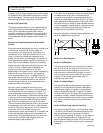
Section 2.1.1.b Creep Speed
With the accelerator at maximum ohms or volts
(approximately 3.7 to 3.5 VDC), the creep speed can be
adjusted by Function 2 of the Handset. At creep speed, the
ON time can decrease to approximately 5%, with the OFF
time at approximately 95%. At full transistor operation, this
condition will be reversed (short OFF time, long ON time).
This variation of ON and OFF time of the oscillator varies
the voltage applied to the motor, thereby varying the speed
of the motor for a given load.
Section 2.1.1.c Control Acceleration
This feature allows for adjustment of the rate of time it
takes for the control to accelerate to 100% applied battery
voltage to the motor on hard acceleration. Armature C/A is
adjusted by Function 3 from 0.1 to 22 seconds.
Section 2.1.2 Current Limit
This circuit monitors motor current by utilizing sensors in
series with the armature and field windings. The
information detected by the sensor is fed back to the card
so that current may be limited to a pre-set value. If heavy
load currents are detected, this circuit overrides the
oscillator and limits the average current to a value set by
Function 4 and Function 8 of the Handset. The C/L setting is
based on the maximum thermal rating of the control.
Because of the flyback current through 3REC, the motor
current is usually greater than battery current, except at
100% ON time.
Section 2.1.3 Braking
Section 2.1.3.a Plug Braking
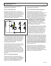
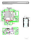
Section 2.1.3.b Regenerative Braking to Zero Speed
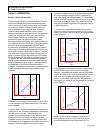
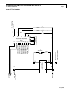
Slow down is accomplished when
reversing direction by providing a
small amount of retarding torque for
deceleration. If the vehicle is
moving, and the directional lever is
moved from one direction to the
other, the regen signal is initiated.
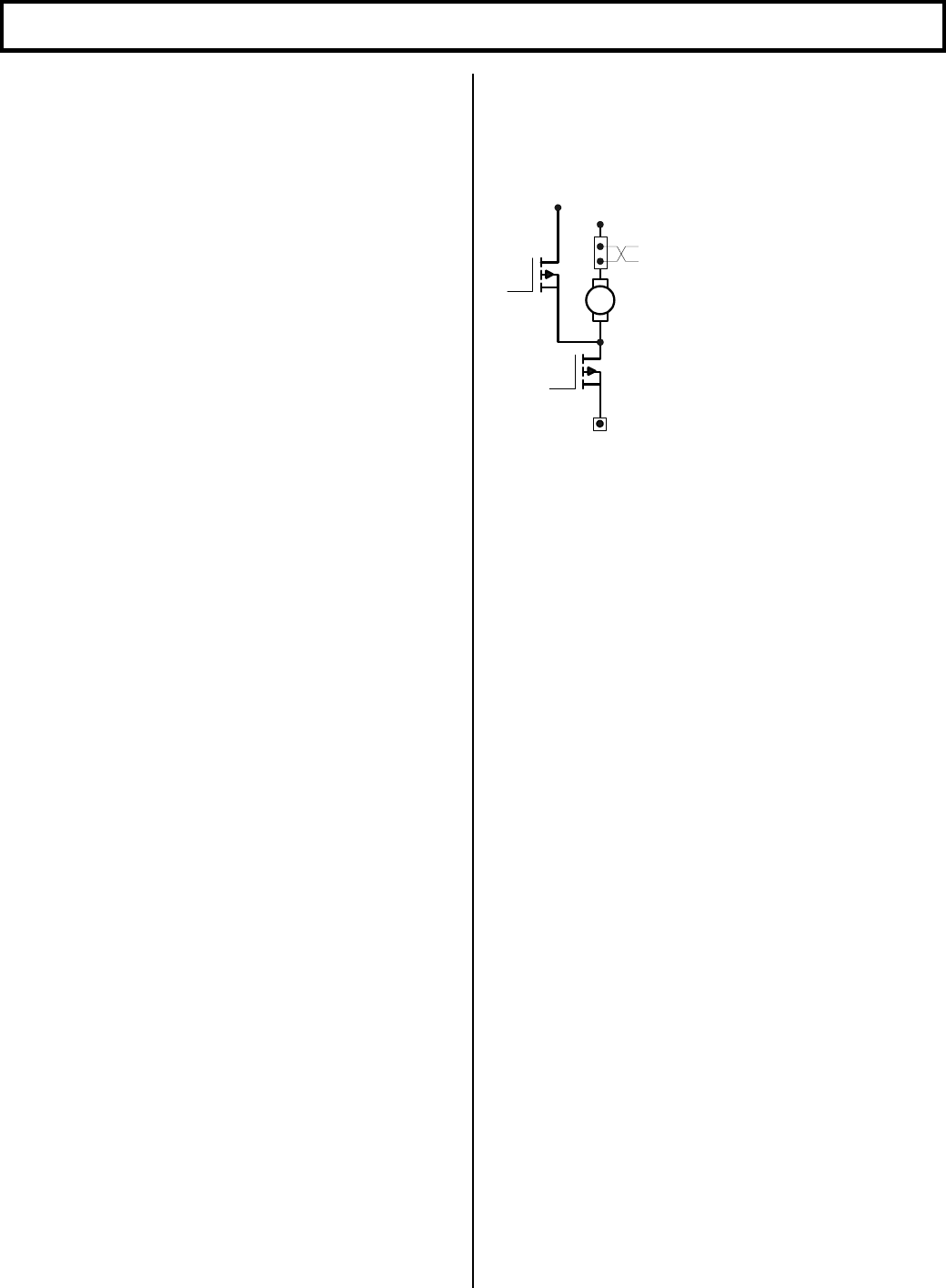
Once the regen signal has been
initiated, the field current is
increased (armature circuit shown in
Figure 5). Armature current is
regulated to the regen current limit as set by Function 9. As
the vehicle slows down, the field current continues to
increase, and transistor Q2 begins to chop. The field
current will increase until it reaches a preset value set by
Function 10, and transistor Q2 on-time will increase until it
reaches 100% on-time. Once both of the above conditions
have been met, and regen current limit can no longer be
maintained, the braking function is canceled. The fields
will then reverse, and the control reverts back to motoring.
Part of the energy produced by the motor during regen is
returned to the battery, and part is dumped in the motor as
heat.
Section 2.1.3.c Pedal Position Plug Braking
This feature allows control of the plugging distance based
on pedal position when there has been a “directional
switch" change. Pedal position will reduce the regenerative
current to the "value set by this function" as the accelerator
is returned to the creep speed position. Maximum regen
current is obtained with the accelerator in the top speed
position.
Section 2.1.3.d Auto Braking
This feature is enabled by initiating a "neutral position"
using either the directional switch or the accelerator
switch. Once activated, Auto Braking operates similar to
Pedal Position Plug Braking and is adjusted by using
Function 21 of the Handset.
Section 2.1.4 Auxiliary Speed Control
Section 2.1.4.a Field Weakening
This function allows the adjustment of the field weakening
level in order to set the top speed of the motor. The function
is enabled when the armature current is less than the value
set by Function 24 and the accelerator input voltage is less
than 1 volt. It is important to note that this function is used
ARM
Q1
Q2
Figure 5