


INSTALLATION AND OPERATION MANUAL
IT/IP TRANSISTOR CONTROL Page 68
January 2001
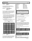
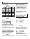
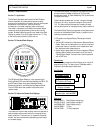
Section 7.4 Start-Up Display Sequence
START-UP DISPLAY SEQUENCE
Key Switch On
Verify Each LED Segment
8 8 8 8
If Maintenance Code
Is
Active
If Maintenance Code
Is Not
Active
Display Code "-99"
For Four Seconds and
Activate Speed Limit
(if selected)
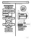
BDI Display or
Blank Display
(no BDI used)
Diagnostics Override
With Fault
Run Mode
BDI Display or
Blank Display
(no BDI used)
Diagnostics Override
With Fault
Key Switch
Off
Display Traction
Hourmeter
For Four Seconds
Display Pump
Hourmeter
For Four Seconds
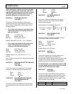
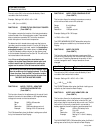
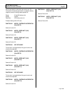
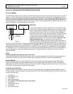
Section 7.5 Outline Drawings
g
GE Electric Vehicle
Motors & Controls
+
-
PY3
PY4
PY2
PY1
PY5
1 2 3 4 5
5 4 3 2 1
PY3
PY4
PY2
PY1
PUMP
TRACTION
BACK VIEW OF DISPLAY
Wiring connections to "Y"
plugs of Traction & Pump
controls.
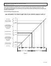
2.45 (62.2)
3.20 (81.3)
0.19
(4.8)
2.00 (50.8)
PUMP
TRACTION
CONNECTOR OMITTED
IF NOT REQUIRED
0.41
(10.4)