


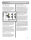

BASIC OPERATION AND FEATURES
SX TRANSISTOR CONTROL Page 7
January 2000
to optimize motor and control performance, and this setting
will be determined by GE and OEM engineers at the time of
vehicle development. This setting must not be changed by
field personnel, without the permission of the OEM.
Section 2.1.4.b Speed Limits
This feature provides a means to control speed by limiting
motor volts utilizing three "adjustable speed limits. This
motor volt limit regulates top speed of the transistor
controller, but actual truck speed will vary at any set point
depending on the loading of the vehicle. Each speed limit
can be adjustable with the Handset using Functions 11, 12,
and 13.
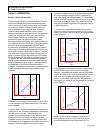
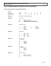
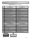
Section 2.1.4.c Proportional Operation for Dual Motor
Vehicles
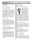
A key performance advantage of this control is the ability to
achieve actual "proportioning" of motor speed. In a
non-proportioning, or single control, system when the
vehicle starts to turn, the outside drive wheel turns in a
larger circle than the inside wheel. Depending on the
geometry of the vehicle, at some degree of turn angle, the
inside wheel must slow down to prevent scrubbing of the
wheel. This is accomplished on single control system by
disconnecting the inside motor and letting the wheel "free
wheel" or "float" at whatever speed is dictated by the
outside wheel that is still under power. The main
disadvantage of this system is that no torque is available on
that motor when the inside wheel is in the "free-wheel"
mode, and performance in a turn is reduced. When the
steer wheel nears to the 90° turn angle, the inside motor is
re-connected in the opposite direction of the outside. At
this point, torque is returned to the inside wheel and the
speed is the same on both motors.
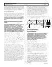
With two controls, the speed of each motor can be
regulated independently. The driver controls the speed of
the outside wheel with the accelerator input signal. The
inside wheel speed is controlled by the turn angle of the
steer wheel . A potentiometer is attached to the steer wheel
in order to communicate the steer angle to the controllers.
During vehicle manufacture, software selection identifies
each control for its application as a right or left control.
The controls are physically identical, and it is only software
that separates a right from a left control or differentiates a
control for a dual motor application from one intended for a
single motor vehicle. As the steer reaches some
pre-selected turn angle, approximately 20
o
, the speed of the
inside wheel decrease proportionally to the speed of the
outside wheel. This proportional decline will continue on a
linear path until the steer angle reaches another pre-
determine angle of, approximately 65
o
.
At this point, the inside wheel will stop, as the steer angle is
increased toward the 90° point, the inside wheel will
reverse direction and start to accelerate proportionally in
speed. As the steer angle reaches the 90° point, the inside
wheel speed will be the same as that of the outside wheel.
During this entire turn, except for several degrees when the
motor was stopped to change direction, torque was always
present on the inside wheel, providing a smoother ride
throughout the turning radius of the vehicle.
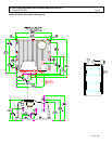
Details for adjustment of the steer angle potentiometer can
be found in Appendix A of this manual.
0
O
10
O
10
O
20
O
20
O
30
O
30
O
40
O
40
O
50
O
50
O
60
O
60
O
70
O
70
O
80
O
80
O
90
O
100%
50%
50%
100%
90
O
100%
50%
50%
100%
RIGHT
MOTOR
LEFT
MOTOR
STEERING ANGLE
LEFT
TURN
RIGHT
TURN
LEFT
MOTOR
RIGHT
MOTOR
RIGHT
CONTROL
LEFT
CONTROL
0
O
90
O
90
O
REV - SPEED - FWD
REV - SPEED - FWD
Section 2.1.5 Ramp Operation
Section 2.1.5a Ramp Start
This feature provides maximum control torque to restart a
vehicle on an incline. The memory for this function is the
directional switch. When stopping on an incline, the
directional switch must be left in its original or neutral
position to allow the control to initiate full power when
restarted. The accelerator potentiometer input will
modulate ramp start current.
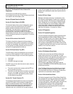
Section 2.1.5b Anti-Rollback
This feature provides retarding torque to limit rollback
speed in the non-travel direction when the ACC pedal is
released when stopping on a grade, or when the brake
pedal is released when starting on a grade. This feature
forces the vehicle to roll very slowly down the grade when
accelerator or brake is released. Because the vehicle can
gain significant speed during roll-back, the torque needed
to re-start on the ramp is lower than an unrestricted roll-
back speed.
Section 2.1.6 Steer Pump Contactor Time Delay
This feature provides two options for SP time delay. Option
1 provides a 0.5 to 63 second time delayed drop out of the
steer pump contactor when the Forward or Reverse
directional switch is opened. This Option 1 is overridden by
a 1.5 second time delayed drop out whenever the seat
switch is opened. Option 2 provides a 0.5 to 63 second time
delayed drop out of the SP contactor when the seat switch
is opened.