


CROSSFADER. Rail Glide™ crossfaders have internal
dual stainless steel rails that allow the slider to ride
smoothly and accurately from end to end. Also available
is our is the RG-45 PRO (RAIL GLIDE™) crossfader with
a special curve designed for scratch mixing. Just pur-
chase one from your GEMINI dealer and follow the
instructions:
NOTE: DO NOT APPLY PRESSURE WHILE USING THE
CROSSFADER. LIGHTLY GLIDE THE CROSSFADER BACK AND
FORTH. PRESSING DOWN ON THE CONTROLS CAN BEND CON-
TACTS AND CAUSE A LOSS OF SOUND.
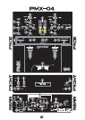
5. The CROSSFADER SLOPE SWITCH (19) allows you to
adjust the kind of slope the crossfader has. Flip the cross-
fader slope switch up to make the slope steep and cutting
(perfect for scratching). Flip the crossfader slope switch
down to make the slope gradual and gentle.
6. The CROSSFADER REVERSE SWITCH (20) allows
you to reverse the crossfader so that CH 2 (32) is con-
trolled by the left side of the crossfader and CH 1 (26) is
controlled by the right side of the crossfader.
7. CUE: The CUE FADER (18) facilitates the seamless
blending of one recorded track into another. Connecting a
set of headphones to the HEADPHONES (16) jack allows
you to monitor either CH 1 (26) or CH 2 (32). Select CH
1 (26) by moving CUE FADER (18), located on the front
panel, to CUE 1 on the left. Listen to CH 2 (32) by mov-
ing CUE FADER (18) to CUE 2 on the right. To mix both
Channels bring CUE FADER (18) to the middle so that
both tracks may be heard. Use CUE VOLUME (17) to
adjust the headphone volume without affecting the speak-
er-driven mix.
8. FILTER/FX SECTION: The PMX-04 is equipped with fil-
ter effects. This means you may augment the cut off fre-
quency of your program mix by filtering out the tonal
boost located in the low, mid, and/or high frequency
range.
To control this section you must adjust the DRY/WET
FADER (34) in order to increase the depth of the filter
effect. Glide the DRY/WET FADER (34) to the right to
increase the filter effect, drowning out the program mix
with a deep, wet effect. Glide the DRY/WET FADER (34)
to the left to decrease the filter effect, thus disabling the
filter effects.
Use the Q FACTOR (35) rotary control to adjust the
effect's frequency volume. Rotate the Q factor (35) rotary
control clockwise to increase the effect's frequency vol-
ume, giving the effect a very sharp, audible cut-off
response. Rotate the Q FACTOR (35) rotary control count-
er-clockwise to decrease the effect's frequency volume,
giving the effect a dull, less audible cut-off response.
Engage the push button TEMPO ON (36) to control the
recycling speed of the filter's effect. Use the TEMPO (37)
rotary control to adjust the recycling speed of the filter's
effect. Rotate the TEMPO (37) rotary control clockwise to
increase the recycling speed of the filter's effect. Rotate
the TEMPO (37) rotary control counter clockwise to
decrease the recycling speed of the filter's effect.
Use the RESONANCE FADER (38) to channel the PGM
through variable cut-off frequency responses. Glide the
RESONANCE FADER (38) to the left to engage the low
pass. You will notice the low frequencies in your program
mix become the focal point in your audio mix. While glid-
ing the RESONANCE FADER (38) to the right, you will
reach the mid pass. Notice how the mid tones become
the focal point in your audio mix when you have reached
the middle. When you have reached the right end of the
RESONANCE FADER (38), you will reach the high pass.
Notice how the treble tones become the focal point in
your audio mix.
NOTE: WHEN USING THE FILTER EFFECT, YOU MAY EXPERIENCE
A TONAL BOOST DURING A HIGH PASS THAT WILL SEND YOUR
MASTER OUTPUT LEVELS INTO THE BLUE (0 THROUGH +11), AS
INDICATED IN YOUR VU METER (40). ADJUST THE CHANNEL
FADERS (26, 32), IN ORDER TO PROTECT YOUR EQUIPMENT
FROM A SYSTEM OVERLOAD. TO BEGIN FILTER EXPERIMENTA-
TION, START WITH A LOW PASS (RESONANCE FADER (38) TO
THE LEFT) WITH YOUR CHANNEL FADERS (26, 32) AT MID LEVEL.
THEN MOVE SLOWLY THROUGH THE MID AND HIGH PASS TO
EXAMINE THE TONAL BOOST, SAFELY.
9. MIC SECTION: Connecting a microphone to the 1/4"
MIC JACK (12) allows voice amplification through the
mixer to the stereo through the MASTER RCA OUTPUTS
(3). This is controlled by the MIC VOLUME (13), HIGH
(14), LOW (15) rotary controls.
10. OUTPUT CONTROL SECTION: The level of the MAS-
TER (4) RCA output is controlled by the MASTER VOL-
UME (39) rotary control.
11. DISPLAYS: The DUAL VU METER (40) indicates the
level of the MASTER (4) RCA output left and right chan-
nel levels respectively. DUAL VU METER (40) reflects the
MASTER VOLUME (39), GAIN (22, 28), HIGH (23, 29),
MID (24, 30) and LOW (25, 31) rotary control adjustments
for each channel. The CH SLIDES (26, 32) also affect
each of the DUAL VU METER (40).
SPECIFICATIONS:
INPUTS:
DJ Mic....................................................1.5 mV 1 kOhm Balanced
Phono......................................................................3 mV 47 kOhm
Line......................................................................150 mV 10 kOhm
OUTPUTS:
Amp....................................................................0 dB 1 V 400 Ohm
Max....................................................................20 V Peak to Peak
GENERAL:
Bass (Channels 1-2).......................................................+12 -32 dB
Mid (Channels 1-2).......................................................+12 - 32 dB
High (Channels 1-2)......................................................+12 - 32 dB
Gain (Channels 1-2)...................................................... 0 to -20 dB
Frequency Response....................................20 Hz-20 kHz +/- 2 dB
Distortion..............................................................Less Than 0.02%
S/N Ratio............................................................Better Than 80 dB
Headphone Impedance.......................................................16 Ohm
Power Source.........................................................115 V/60 Hz AC
...........................................................................or 230 V/50 Hz AC
Unit Dimensions.....W 10" x H 3.3" x D 10.25" (254 x 84 x 260 mm)
Weight...................................................................7.48 lbs ( 3.4 kg)
NOTE: SPECIFICATIONS AND DESIGN ARE SUBJECT TO CHANGE
WITHOUT NOTICE FOR PURPOSE OF IMPROVEMENT.
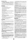
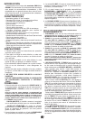
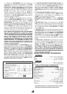
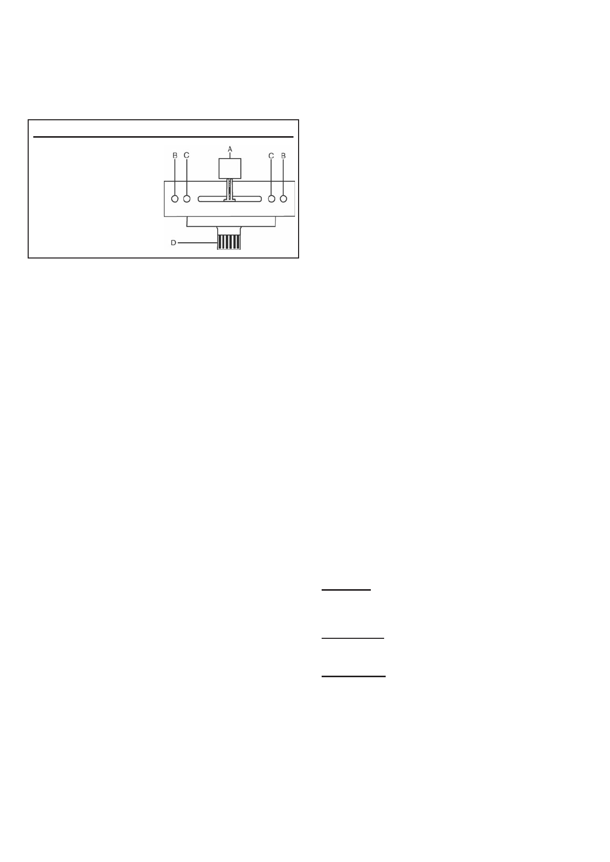
USER REPLACEABLE CROSS FADER
1. Unscrew the outside mixer FACE
PLATE screws and remove the
face plate. Then remove FADER
plate screws (B & C).
2. Carefully lift the fader and unplug
the CABLE (D).
3. Plug the new fader into the
cable and place it back in the
mixer.
4. Screw fader plate to the mixer
and replace the mixer FACE
PLATE.
(5)