


-15-
REAR PANEL CONTROLS
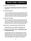
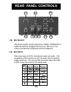
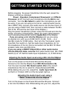
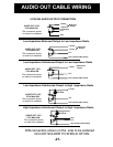
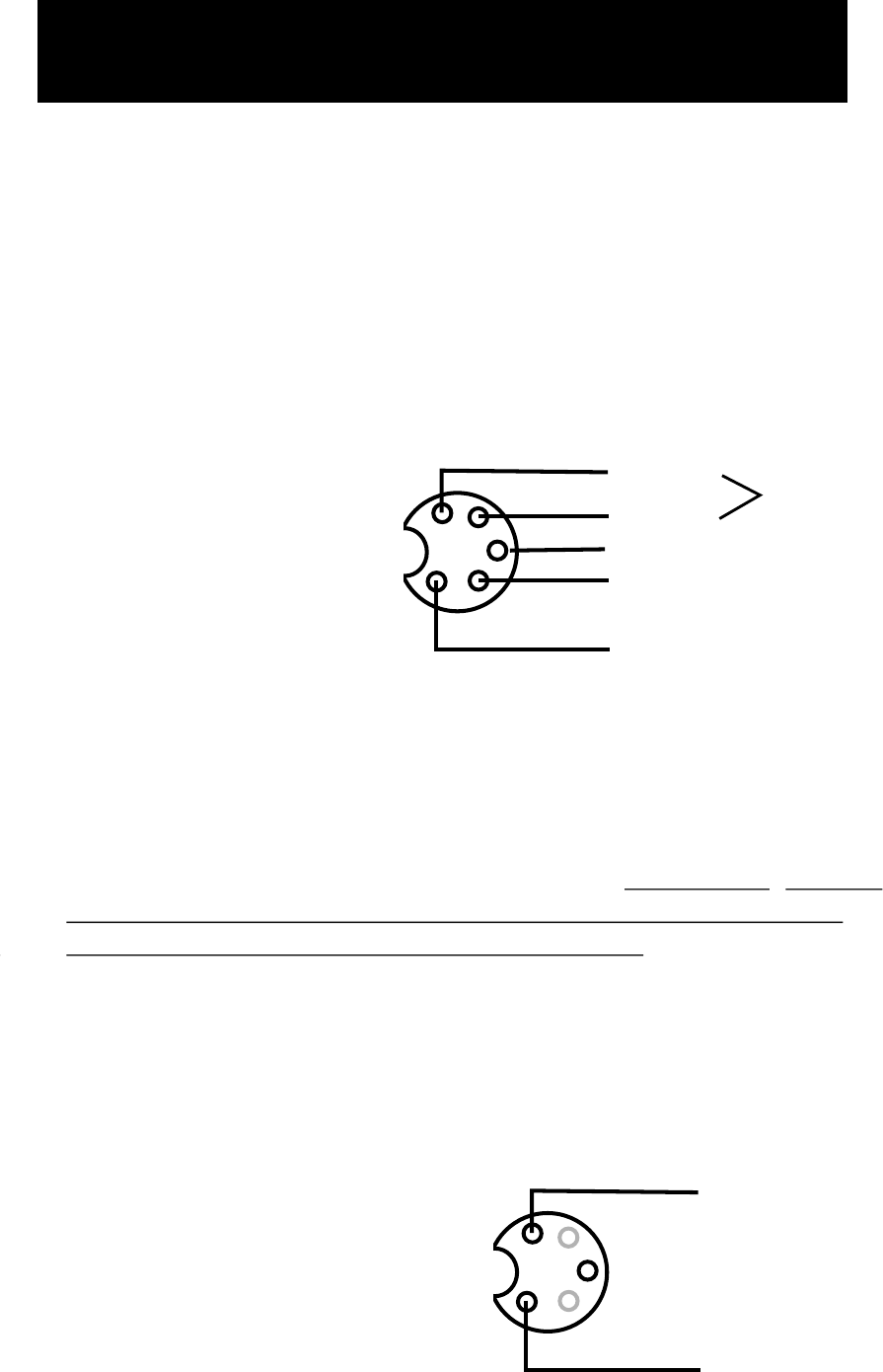
(23) AUDIO OUTPUTS 1,2 and 3
The audio output and PTT outputs of the EQplus uses these
5 pin DIN’s. When the Audio Output Rotary switch (22) is in
the “1” position, audio is active at Audio Output 1. When the
Audio Output Rotary switch (22) is in the “2” position, audio
is active at Audio Output 2. When the Audio Output Rotary
Switch (22) is in the “3” position, audio is active at Audio
Output 3. The diagram below shows the configuration of each
of the 3 outputs.
(24) PHONES
This 1/4“ Stereo headphone connector can be used to monitor
audio from the EQplus. The output level of this connector is
controlled by the Monitor Level control(1). Important: Unless
headphones using 1/4” stereo connectors are used, the
EQplus monitor will not operate properly.
(An inline adapter should be used with headsets that do not
use 1/4“ stereo connectors. Stores like Radio Shack have
such adapters available.)
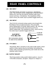
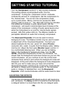
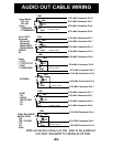
(25) Power
5 Pin Din connector. 7 - 14 VDC input at 100 ma.
Gnd
PTT
- Audio
+ Audio
Balanced
Output
Hi-Z Output
AUDIO OUT 1/2/3
5 Pin Male DIN
Din connectors shown
on side to be soldered
+7 to 14V
GND
Power
5 Pin Male DIN
Din connectors shown
on side to be soldered