©2007, Shure Incorporated
27H2831 (Rev. 2)
Printed in U.S.A.
GENERAL
Shure Microflex
®
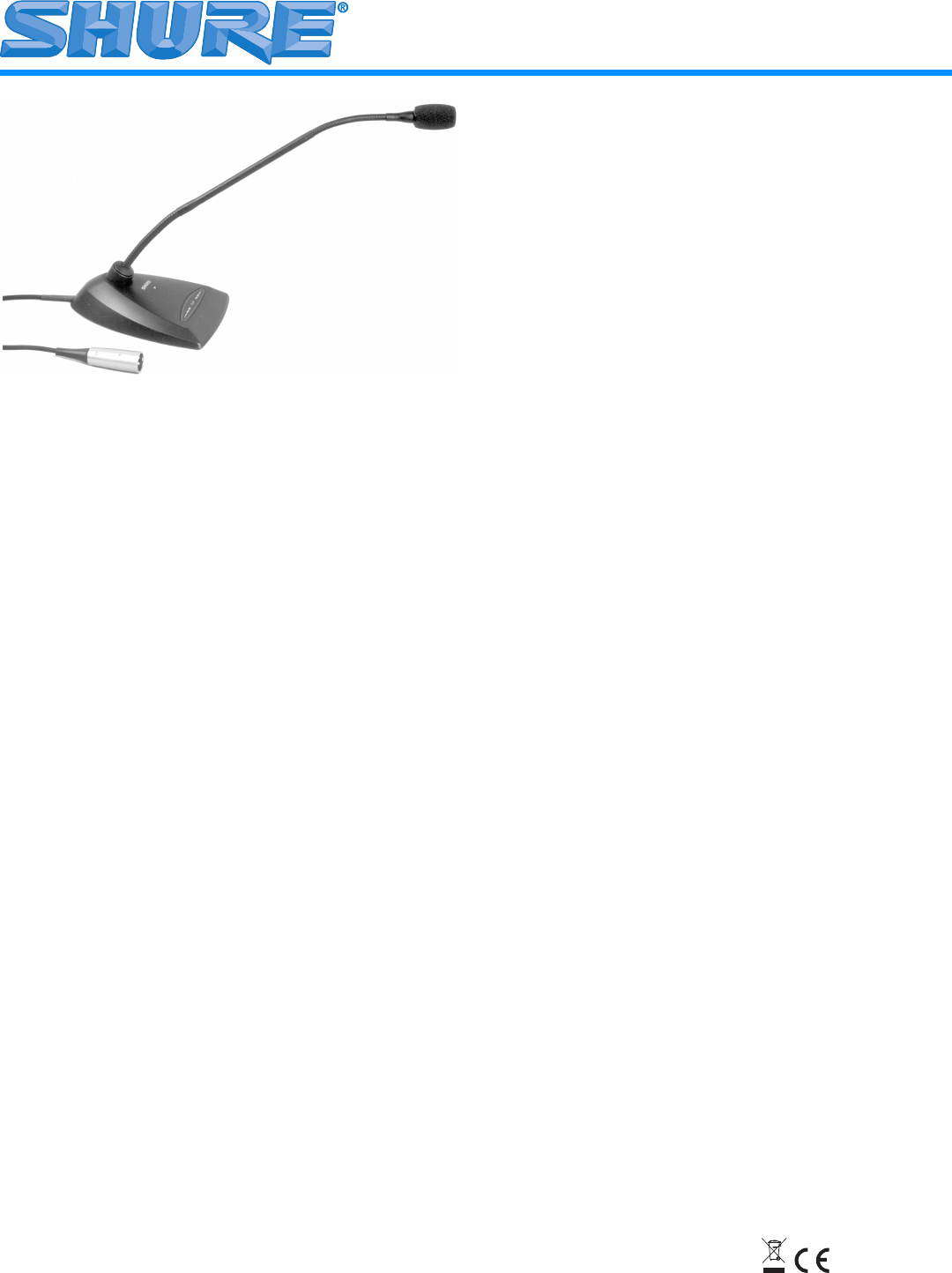
MX400D Series microphones are miniature
electret condenser gooseneck microphones with a desktop base
and attached 3 m (approximate)/10 ft cable. The desktop base
allows these microphones to be used in multi-purpose rooms
where quick set-up is required, or where permanent installation
is impractical.
FEATURES
• Wide dynamic range and frequency response for accurate
sound reproduction across the audio spectrum
• Interchangeable cartridges provide the right polar pattern
for any application
• Balanced, transformerless output for increased immunity to
noise over long cable runs
• Programmable on/off switch and LED on/off indicator
• New brighter LED improves visibility under strong ambient
lighting
• Logic input and output terminals for remote control or use
with automatic microphone mixers
• Snap-fit foam windscreen
• New RF filtering
MODEL VARIATIONS
MX412D: 304.8 mm (12 in.) desktop mini-condenser, goose-
neck-mounted microphone.
MX418D: 457.2 mm (18 in.) desktop mini-condenser, goose-
neck-mounted microphone.
SELECTING A POLAR PATTERN
All Microflex microphones are available with any one of three inter-
changeable cartridges. The polar pattern of the cartridge is indicat-
ed by the model number suffix:
/C = Cardioid, /S = Supercardioid, /O= Omnidirectional
Cardioid (C). Recommended for general sound reinforcement ap-
plications. Pickup angle (-3 dB) = 130°.
Supercardioid (S). Recommended for sound reinforcement appli-
cations requiring narrower or more distant coverage. Pickup angle
(-3 dB) = 115°.
Omnidirectional (O). Recommended for recording or remote
monitoring applications. Pickup angle = 360°.
GENERAL INSTALLATION GUIDELINES
1. Aim the microphone toward the desired sound source, such as
the talker, and away from any unwanted sound source, such as
a loudspeaker.
2. Place the microphone cartridge within 15 to 30 cm (6 to 12 in.)
of the desired sound source.
3. Always use the supplied windscreen or the optional metal
windscreen to control breath noise.
4. If four or more microphones will be on at the same time, use of
an automatic mixer, such as the Shure SCM810 or FP410, is
recommended to minimize feedback and noise.
MICROPHONE INSTALLATION
Securing a Microphone to a Mounting Surface (Figure 1
on page 11)
1. Install two #6-32 screws, 50.8 mm (2 in.) apart starting from the
bottom of the mounting surface.
2. Drill screw-mounting holes through table. Remove debris from
hole.
3. Place unit on table with the holes lined up.
4. Tighten the screws into the threaded holes to secure the
microphone.
Installing the Foam Windscreen (Figure 2 on page 11)
1. Press the foam windscreen onto the microphone until it snaps
into the groove located below the cartridge.
2. To remove the windscreen, spread the slot in its mounting ring
with a screwdriver or thumbnail and pull the windscreen off
carefully.
INTERNAL DIP SWITCH FUNCTIONS
All MX400D models have internal DIP switches that allow the user
to program the On/Off switch for a variety of applications. To gain
access to the DIP switches, remove the bottom plate.
LOGIC TERMINAL DEFINITIONS
LOGIC GND Terminal: Connects to the logic ground of an auto-
matic mixer, switcher, or other equipment.
SWITCH OUT Terminal: Provides a TTL logic low (0 Vdc) when
the membrane switch is pressed. Provides TTL logic high (5 Vdc)
otherwise. This signal is available at all times for all switch settings.
The Switch Out function provides momentary closure when S1 is
Off and latching closure when it is On.
LED IN Terminal: Can be modified to remotely control the LED by
flipping DIP switch S3 in the microphone to the ON position. As
supplied, the LED IN terminal draws 5 Vdc. When this is shorted to
the LOGIC GROUND terminal, the LED turns on.
Microflex
®
MX400D Series
Desktop Microphones User Guide


