


112 Other Functions
01V96i—Reference Manual
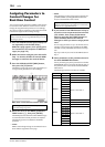
Bus signals via the ADAT IN and OUT connectors and
two 8-channel digital I/O cards (such as MY8-AT).
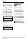
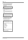
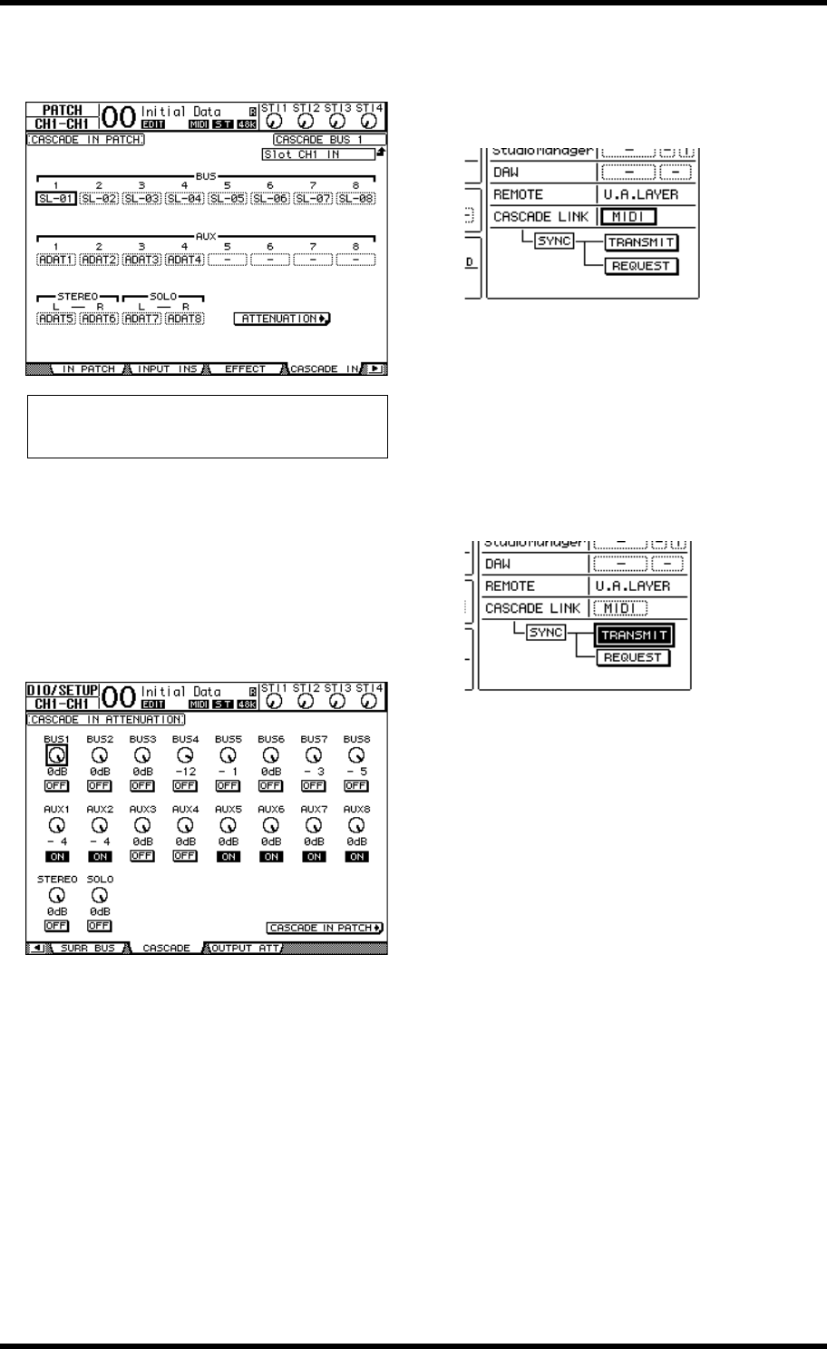
7. On the master unit, press the DISPLAY
ACCESS [DIO/SETUP] button repeatedly until
the DIO/Setup | Cascade page appears, then
adjust the Attenuators using the parameter
controls.
The DIO/Setup | Cascade page enables you to adjust the
level of signals input to the Cascade Bus using the dedi-
cated attenuators. You can also turn the Cascade Buses on
or off using the buttons below the parameter controls.
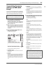
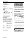
8. Press the DISPLAY ACCESS [DIO/SETUP] but-
ton repeatedly to display the DIO/Setup |
MIDI/Host page, then set the Cascade Link
parameter to “MIDI.”
9. Repeat Step 8 for the master unit.
After Steps 8 and 9, the slave unit will be able to transmit
and receive MIDI messages.
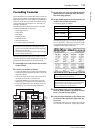
10.
To match the parameters of both 01V96is,
locate the DIO/Setup | MIDI/Host page on
the copy source unit.
Move the cursor to the TRANSMIT button for
the SYNC parameter, then press [ENTER].
Parameters for cascade link (page 111) will be copied to
the other 01V96i via the REMOTE connector. If you
select the REQUEST button instead of the TRANSMIT
button for the SYNC parameter, you can reverse the copy
direction.
At this point, Bus 1–8, Aux 1–4, and the Stereo Bus on
both 01V96is are integrated, and the data is output via
Bus Outs 1–8, Aux Outs 1–4, and the Stereo Out on the
master unit. If you solo channels on one of the 01V96is,
you can monitor the soloed signals via the Monitor out-
puts.
Note: Be sure to patch the slave Bus signals to the same Buses
on the master unit. Incorrect patching will result in an incor-
rect cascade connection.