


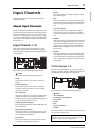
24 Input Channels
01V96i—Reference Manual
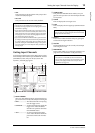
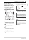
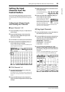
7 DELAY section (*)
This section enables you to set the currently-selected
channel’s Delay function. (See page 18 for more informa-
tion.)
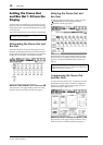
8 PAIR section (*)
This section indicates whether or not channels are paired.
The heart icon ( ) is in one piece when channels are
paired. The heart icon is broken ( ) when channels are
not paired. (See page 26 for more information.)
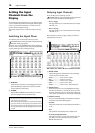
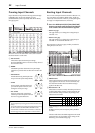
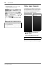
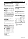
■ Viewing the Pan, Fader, and Aux
Send Level Settings
To display the View | Fader page of a certain Input Channel,
use the corresponding [SEL] button to select the desired
channel, then press the DISPLAY ACCESS [VIEW] button
repeatedly.
Move the cursor to a parameter you wish to change, then
rotate the Parameter wheel or press the [INC]/[DEC] buttons
to modify the setting.
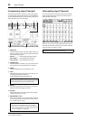
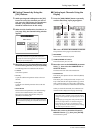
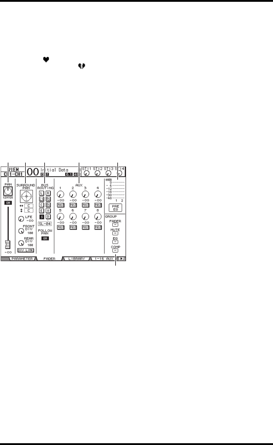
1 PAN/ON/Fader section
•PAN control
This control adjusts the currently-selected Input Chan-
nel’s Pan parameter.
Press the [ENTER] button to reset the Pan control to
Center.
• ON/OFF button
This button turns on or off the currently-selected Input
Channel.
•Fader
This parameter sets the fader position of the cur-
rently-selected Input Channel. The fader knob is high-
lighted when the fader is set to 0.0 dB.
Press the [ENTER] button to reset the Fader to 0.0 dB.
2 SURROUND PAN section
• SURROUND PAN
The Surround pan parameters for the currently-selected
Input Channel are displayed only when a Surround mode
is selected. See page 52 for more information on Sur-
round pan.
3 BUS ROUTING/FOLLOW PAN section
•BUS ROUTING
This section enables you to select a destination Bus for the
selected channel. When the D button is turned on, the
channel signal is patched to the Direct Out selected in the
parameter box below the button. (The D button is
unavailable for the ST IN Channels.)
• FOLLOW PAN
This button determines whether the Input Channel’s Pan
setting is applied to the paired Bus Outs (Follow Pan
function). When the button is turned off, the Follow Pan
function is disabled and an identical signal is sent to the
paired Bus Outs. In surround mode, it also determines
whether the Surround Pan setting is applied to the Bus
Outs.
4 AUX section
•AUX
These controls set the currently-selected Input Channel’s
Aux Send 1–8 levels and positions. (See page 36 for more
information on Aux Sends.)
5 Meter section
•Meters
These meters indicate the levels of the currently-selected
Input Channel.
• PRE EQ/PRE FADER/POST FADER
The metering position is displayed below the meters.
6 GROUP section
• FADER/MUTE/EQ/COMP
These buttons indicate which Fader, Mute, EQ, or Comp
group, if any, the currently-selected Input Channel is in. If
the channel is in a group, the group number appears. If
the channel is not in a group, “—” appears. (The compres-
sor is unavailable for the ST IN Channels.)
321 4 5
6