


Bus Outs 29
01V96i—Reference Manual
Bus Outs
Bus Outs
This chapter describes how to adjust the 01V96i’s Stereo Out
and Bus Out 1–8 parameters.
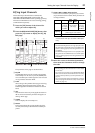
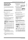
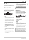
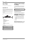
About Stereo Out
The Stereo Out section receives Input Channel and Bus Out
1–8 signals, mixes them into two channels, processes them
using on-board EQ, compressor, etc., then routes them to the
STEREO OUT and 2TR OUT connectors. The following dia-
gram illustrates the Stereo Out signal flow.
•INSERT
This section enables you to route the Stereo Out signals to
external devices via the on-board connectors or I/O card,
or insert internal effects processors.
•ATT (Attenuator)
This section enables you to attenuate or amplify the level
of signals to be input to the EQ. The attenuator prevents
post-EQ signals from clipping or corrects signal levels
that are too low.
• 4 BAND EQ (4-band equalizer)
This parametric EQ features four bands (HIGH,
HIGH-MID, LOW-MID, and LOW).
•COMP (Compressor)
This dynamics processor can be used as compressor,
expander, or limiter. The processor can be located
pre-EQ, pre-[STEREO] fader, or post-[STEREO] fader.
• ON (On/Off)
This button turns the Stereo Out on or off.
•LEVEL
The [STEREO] fader adjusts the Stereo Out output levels.
•Balance
This section enables you to adjust the level balance
between the L and R channels of the Stereo Out.
•OUTPUT DELAY (Output delay)
This section delays the output signals. It is mainly used to
fine-tune the signal timing.
• METER
This section enables you to switch the metering position
of signal levels that are displayed on the Meter page or by
the stereo meter to the right of the screen.
For more information on selecting the metering position,
refer to “Viewing the Level Meters” in the Owner’s Man-
ual (booklet).
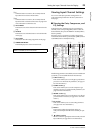
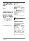
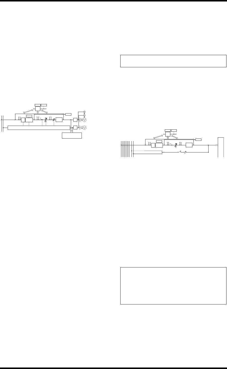
Bus Out 1–8
The Bus Out 1–8 section mixes signals routed from Input
Channels to the specified buses, processes them using
on-board EQ, compressor, etc., then routes them to the spec-
ified output connectors or I/O card.
The following diagram illustrates the Bus Out signal flow.
•INSERT
•ATT (Attenuator)
• 4 BAND EQ (4-band equalizer)
•COMP (Compressor)
• ON (On/Off)
•LEVEL
•OUTPUT DELAY (Output delay)
• METER
The parameters and sections listed above are identical to
those for the Stereo Out. For more information, refer to
the explanation of the Stereo Out.
•Bus to Stereo
Bus Out 1–8 signals are also routed to the Stereo Bus. In
addition to the ON, LEVEL, and other parameters, you
can also set the Send Level, On/Off, Pan, and other
parameters.
OUTPUT PATCH
OUTPUT
DELAY
METER
ATT
4BAND
EQ
INSERT
INSERT
LEVEL
ON
COMP
METER
(Gain Reduction)
BAL
INSERT
Same as stereo master L
METER
METER
(Out Meter)
STEREO L
STEREO R
[STEREO OUT]
L
R
(+4dBu)
L
R
(-10dBV)
DA
DA
[2TR OUT]
Note: You can also patch the Stereo Out signals to other output
connectors or the I/O card by using the Patch | Out Patch pages.
Tip:
• You can also pair adjacent odd-even buses for stereo operation
(see page 33).
• By default, Slot channels 1–8 and 9–16 and ADAT OUT chan-
nels 1–8 are patched to the Bus Out 1–8 outputs. However, you
can change this patching on the Patch | Out Patch page (see
page 44).
OUTPUT PATCH
OUTPUT
DELAY
METER
ATT
4BAND
EQ
INSERT
INSERT
LEVEL
ON
COMP
METER
(Gain Reduction)
INSERT
METER
METER
(Out Meter)
STEREO L
STEREO R
BUS1
BUS2
BUS3
BUS4
BUS5
BUS6
BUS7
BUS8
PAN
BUS to STEREO
LEVEL
ON
BUS 1(...8)