


36 Aux Outs
01V96i—Reference Manual
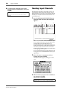
Aux Outs
This chapter describes how to control Aux Out 1–8.
Aux Out 1–8
The Aux Out 1–8 section mixes signals routed from the Input
Channels to the corresponding Aux Sends, processes them
using on-board EQ, compressor, etc., then routes them to the
specified internal effects processors, output connectors or I/O
card connectors.
The 01V96i features eight Aux Sends, which can be used to
send signals to the internal and external effects processors
and monitors.
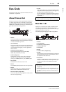
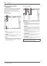
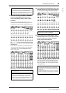
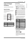
The following diagram illustrates the Aux Out 1–8 signal
flow.
•INSERT
• ATT (Attenuator)
• 4 BAND EQ (4-band equalizer)
•COMP (Compressor)
• ON (On/Off)
•LEVEL
• OUTPUT DELAY (Output delay)
• METER
These parameters are the same as the Stereo Out and Bus Out
1–8 (see page 29).
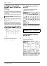
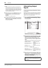
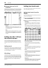
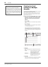
Setting Aux Out 1–8 from
the Display
To set Aux Out 1–8 parameters, you can either move the cur-
sor to the desired parameter on the screen and change the
value, or operate the desired button or control on the top
panel.
This section explains how to set the parameters on the screen.
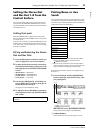
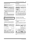
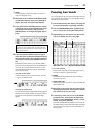
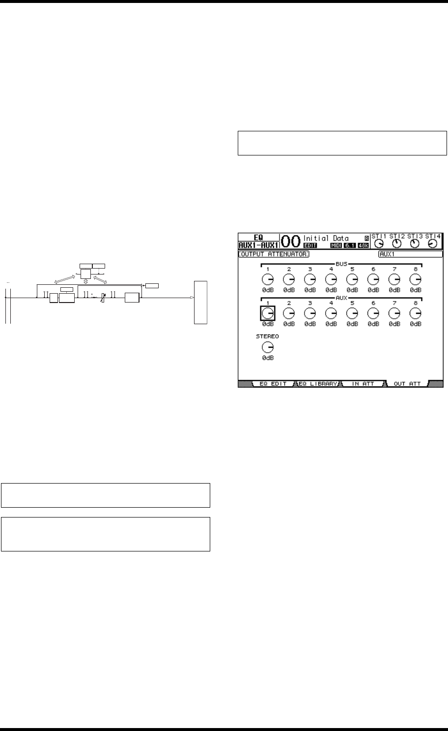
Attenuating Aux Outs
To attenuate Aux Out 1–8 signals, press the [EQ] button, then
press the [F4] button to display the EQ | Out Att page.
The parameters on this page (and the procedure for setting
them) are the same as for Input Channels (see page 20).
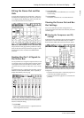
Tip: You can also pair adjacent odd-even Aux Sends (in this
order) for stereo Aux operation.
Note: With the default setting, Aux Out 1–4 are patched to OMNI
OUT connectors 1–4 and to internal Effects processors 1–4. How-
ever, you can change this patching on the Patch | Output page.
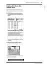
OUTPUT PATCH
OUTPUT
DELAY
METER
ATT
4BAND
EQ
INSERT
INSERT
LEVEL
ON
COMP
METER
(Gain Reduction)
INSERT
METER
METER
(Out Meter)
AUX 1(...8)
AUX 1
AUX 8
Tip: Refer to “Input & Output Patching” on page 43 for more
information on how to set inserts.