


44 Input & Output Patching
01V96i—Reference Manual
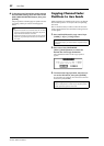
3. Press [ENTER] to confirm the change.
Output Patching
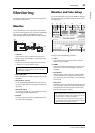
The 01V96i’s Stereo Out, Bus Out 1–8, Aux Out 1–8 signals
can be patched to any outputs, ADAT OUT output channels,
and slot output channels.
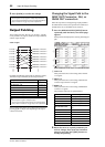
Patch example:
By default, the following signal paths are patched to outputs,
ADAT OUT output channels, and slot output channels:
You can change these patches, if you desire. The procedure for
patching signals to output varies depending on the output
connectors and slots.
Changing the Signal Path to the
ADAT OUT Connector, Slot, or
OMNI OUT connectors
Follow the steps below to change the signal path patched to
the ADAT OUT connector, the optional mini-YGDAI card
installed in the slot, or the OMNI OUT connectors.
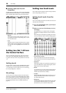
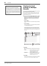
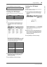
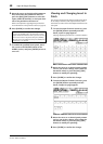
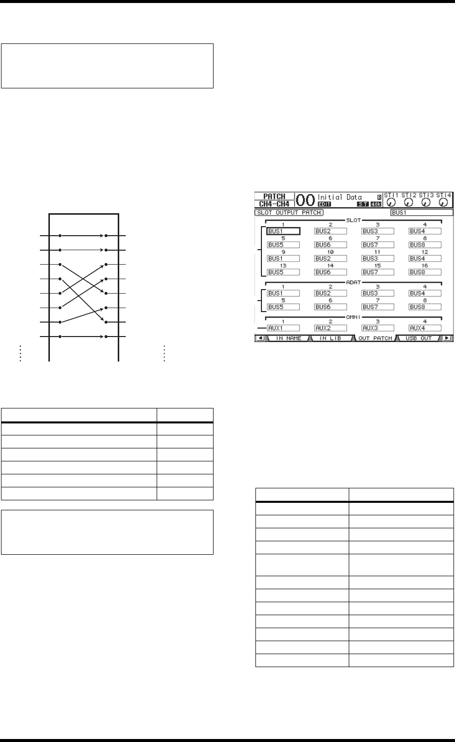
1. Press the DISPLAY ACCESS [PATCH] button
repeatedly until the Patch | Out Patch page
appears.
Each parameter box displays the currently-patched signal
path.
1 SLOT 1–16
These parameter boxes set the routing of Slot Channel
1–16 signals.
2 ADAT 1–8
These parameter boxes set the routing of ADAT OUT
connector output channel 1–8 signals.
3 OMNI 1–4
These parameter boxes set the routing of OMNI OUT
connector 1–4 signals.
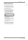
The parameter indicators are explained below:
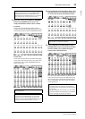
2. Move the cursor to a patch parameter you
wish to change, then rotate the Parameter
wheel or press the [INC]/[DEC] buttons to
modify the patching.
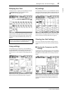
Tip:
• You can patch an input signal to multiple Input Channels.
• You can store the Input Patch settings to the Input Patch library.
Refer to “Libraries” on page 74 for more information.
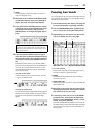
Output connectors and slot channels Signal flow
ADAT OUT output channels 1–8 Bus Outs 1–8
Slot Channels 1–8 Bus Outs 1–8
Slot Channels 9–16 Bus Outs 1–8
OMNI OUT connectors 1–4 Aux Outs 1–4
2TR OUT DIGITAL (L) Stereo Out L
2TR OUT DIGITAL (R) Stereo Out R
Tip:
• You can patch a signal to multiple outputs.
• You can store the Output Patch settings to the Output Patch
library. Refer to “Libraries” on page 74 for more information.
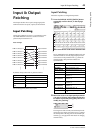
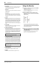
Output Patching
Aux Out 1
Aux Out 2
Aux Out 3
Aux Out 4
Aux Out 5
Aux Out 6
Aux Out 7
Aux Out 8
OMNI Out connector 1
OMNI Out connector 2
OMNI Out connector 3
OMNI Out connector 4
OMNI Out connector 1
OMNI Out connector 2
OMNI Out connector 3
OMNI Out connector 4
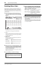
Parameter value Description
– No assignment
BUS1–BUS8 Bus Out 1–8 signal
AUX1–AUX8 Aux Out 1–8 signal
ST L/R Stereo Out signal
INS CH1–INS CH32
Input Channel 1–32 Insert
Out
INS BUS1–INS BUS8 Bus Out 1–8 Insert Out
INS AUX1–INS AUX8 Aux Out 1–8 Insert Out
INS ST-L/ST-R Stereo Out Insert Out
CAS BUS1–BUS8 Bus 1–8 Cascade Outs
CAS AUX1–AUX8 Aux Bus 1–8 Cascade Outs
CAS ST-L/ST-R Stereo Bus Cascade Outs
CASSOLOL/CASSOLOR Solo Bus Cascade Outs
1
2
3