


Insert Patching 47
01V96i—Reference Manual
Input & Output Patching
Insert Patching
The 01V96i’s Input Channels and Output Channels (Stereo
Out, Bus Out 1–8, Aux Out 1–8) feature independent Insert
Ins and Outs. Inputs, outputs, ADAT connector channels, slot
channels, and internal effects processor inputs and outputs
can be patched to the Output Channel Insert Ins and Outs. In
this way, you can send the signals to external effects proces-
sors for processing, or insert internal effects.
Individual Insert Patching
You can patch the 01V96i’s inputs, outputs, ADAT connector
channels, slot channels, and effects processor inputs and out-
puts to the Insert Ins and Outs. The same procedure applies
to both Input Channels and Output Channels.
1. Press the [SEL] button of an Input Channel or
Output Channel for Insert patching.
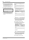
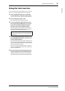
2. Press the [ /INSERT/DELAY] button repeat-
edly until the /INS/DLY | Insert page
appears.
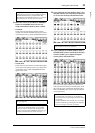
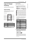
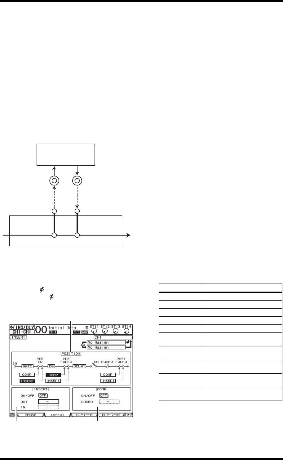
This page contains the following parameters:
1 POSITION
This parameter determines the insert position of the
Insert patch or compressor. The insert position is indi-
cated by highlighted COMP or INSERT buttons.
2 INSERT section
•ON/OFF
This button turns the Insert on or off.
•OUT
This parameter enables you to select outputs, ADAT
OUT channels, slot output channels, or internal effects
inputs as the Insert Out destination.
•IN
This parameter enables you to select inputs, ADAT IN
channels, slot input channels, or internal effects outputs
as the Insert In source.
3 COMP section
•ON/OFF
This button turns the compressor on or off.
•ORDER
This parameter determines the order of Insert patch and
compressor when they are inserted at the same signal
path point. With the “COMP → INS” setting, signals pass
through the compressor first, then the Insert. With the
“INS → COMP” setting, signals pass through the Insert
first, then the compressor.
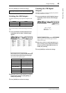
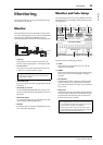
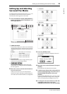
3. Move the cursor to the OUT parameter box,
then rotate the Parameter wheel or press the
[INC]/[DEC] buttons to select the desired out-
puts, slot channels, or internal effects inputs
to be patched to Insert Out.
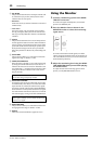
The parameter indicators are explained below:
4. Press [ENTER] to confirm the change.
If you move the cursor to another parameter box or dis-
play another page before you press the [ENTER] button,
all settings on this page will be cancelled.
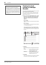
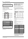
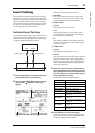
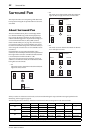
Effects
Input Output
Output connector Input connector
Insert Out Insert In
Channel
1
23
Parameter values Description
– No assignment
ADAT 1–ADAT 8 ADAT OUT Output Channels 1–8
SL-01–SL-16 Slot Channels 1–16
OMNI1–OMNI4 OMNI OUT connectors 1–4
2TD-L/2TD-R 2TR OUT DIGITAL (L/R)
FX1-1/FX1-2
Inputs 1 & 2 of Internal Effects
Processor 1
FX2-1/FX2-2
Inputs 1 & 2 of Internal Effects
Processor 2
FX3-1/FX3-2
Inputs 1 & 2 of Internal Effects
Processor 3
FX4-1/FX4-2
Inputs 1 & 2 of Internal Effects
Processor 4
USB1–USB16
TO HOST USB port output chan-
nels 1–16