


Setting Up and Selecting Surround Pan Modes 55
01V96i—Reference Manual
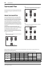
Surround Pan
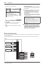
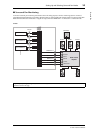
■ Surround Pan Monitoring
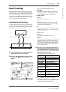
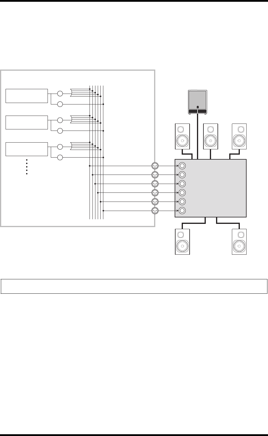
To monitor surround pan movement, patch the Bus Outs to the analog outputs, to which a monitoring system is connected.
The following diagram illustrates an example in which Bus Out 1/2 (left and right front channel) signals are output from the STE-
REO OUT L/R connectors and Bus Out 3–6 signals are output from the OMNI OUT 1–4 connectors in 5.1 Surround mode.
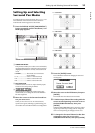
Tip: To output left and right front signals of the surround channels from the STEREO OUT L/R connectors, turn on the Surround LR to Stereo
checkbox on the Surr Bus page.
BUS1 (L)
BUS2 (R)
BUS3 (Ls)
BUS4 (Rs)
BUS5 (C)
BUS6 (LFE)
SURROUND
PAN
LFE LEVEL
SURROUND
PAN
LFE LEVEL
SURROUND
PAN
LFE LEVEL
STEREO OUT L
Front L Front R
Rear L Rear R
Center
Subwoofer
01V96i
STEREO OUT R
OMNI OUT 1
OMNI OUT 2
OMNI OUT 3
OMNI OUT 4
Multi-channel
amplifier
Front L
Front R
Rear L
Rear R
Center
Subwoofer
Input Channel 2
Input Channel 1
Input Channel 3