


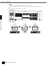
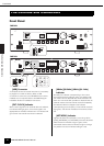
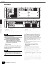
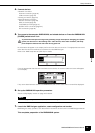
The Controls and Connectors
Front Panel
DME64N/DME24N Owner’s Manual
15
[MIDI] Indicator
Lights while data communication is occurring via the
[MIDI] connector. Received data causes the indicator to
light green, while transmitted data causes the indicator
to light orange. The indicator will light green when
reception and transmission occur simultaneously. If a
problem occurs the indicator will light red.
[MASTER] Indicator
Lights green when the device is operating as the device
group master (page 9). The indicator will not light if the
device is operating as a device group slave. Refer to
page 45 for device group master setup instructions.
[PEAK] Indicator (DME24N only)
Light red when a signal on the corresponding built-in
analog audio input or output ([IN] and [OUT]
connectors) reaches or exceeds -3 dB.
[SIGNAL] Indicator (DME24N only)
Light green when a signal with a level greater than -40
dB is present at the built-in analog audio inputs and
outputs ([IN] and [OUT] connectors).
[SCENE NUMBER] Indicator
Shows the current scene number.
Display
Displays scene information and device parameters.
[SCENE] Button
Calls the scene recall/store display (page 39). The
scene store display will appear if the button is held for
longer than 2 seconds (page 40). The indicator will light
green while the scene recall or store display is showing.
[HOME] Button
Directly recalls the home (main) display. If pressed while
the main display is showing the [HOME] button steps
through the user-defined parameter display pages (refer
to page 38 in this manual).
[UTILITY] Button
Calls the output level display. If this button is held for
longer than 2 seconds while the main display is showing
the utility display will appear. Switches between the
Utility display pages if pressed while the Utility display is
showing.
[LEVEL] Button
Calls the output level setup display (page 39).
The indicator will light green.
[MUTE] Button
Calls the mute display (page 39). The indicator will light
orange when mute is on. The indicator will light green
when mute is off and the mute display is showing, and
will be off if the mute display is not showing.
Dial
Adjusts the value of selected parameters.
[ E ] [ ] [ ] [ F ] Buttons
Move the display cursor in the corresponding directions.
[CANCEL] Button
Closes the window on the display.
[ENTER] Button
Confirms and enters a value or setting.
[PHONES] Jack
A pair of headphones can be plugged in here.
[PHONES LEVEL] Control
Adjusts the headphone volume. Even when the control is
set to the minimum level, the sound at the headphones is
not completely muted.
[MONITOR] Button
Calls the monitoring point slot selection display (page
40). When the [ENTER] button is pressed to select a slot,
the monitoring point selection display will appear.
The spectrum analyzer display will then appear when the
[ENTER] button is pressed to select a monitoring point.
The indicator will light green while the monitoring slot/
point or spectrum analyzer display is showing.
[POWER] Switch
Turns mains power to the device on and off.
NOTE
The DME64N has no built-in analog audio inputs or
outputs ([IN] and [OUT] connectors).
Even when the power switch is turned off,
electricity is still flowing to the product all the
minimum level. When you are not using the
product for a long time, make sure to unplug
the power cord from the wall AC outlet.
CAUTION