


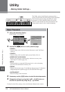
114 CVP-509/505/503/501 Owner’s Manual
CVP-503: Keyboard Stand Assembly
3
CVP-503: Keyboard Stand
Assembly
CAUTION
• Assemble the stand on a hard and flat floor with ample space.
• Be careful not to confuse parts, and be sure to install all parts in the correct direc-
tion. Please assemble in accordance with the sequence given below.
• Assembly should be carried out by at least two persons.
• Be sure to use the correct screw size, as indicated below. Use of incorrect screws
can cause damage.
• Be sure to tighten up all screws upon completing assembly of each unit.
• To disassemble, reverse the assembly sequence given below.
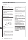
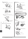
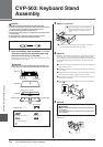
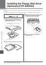
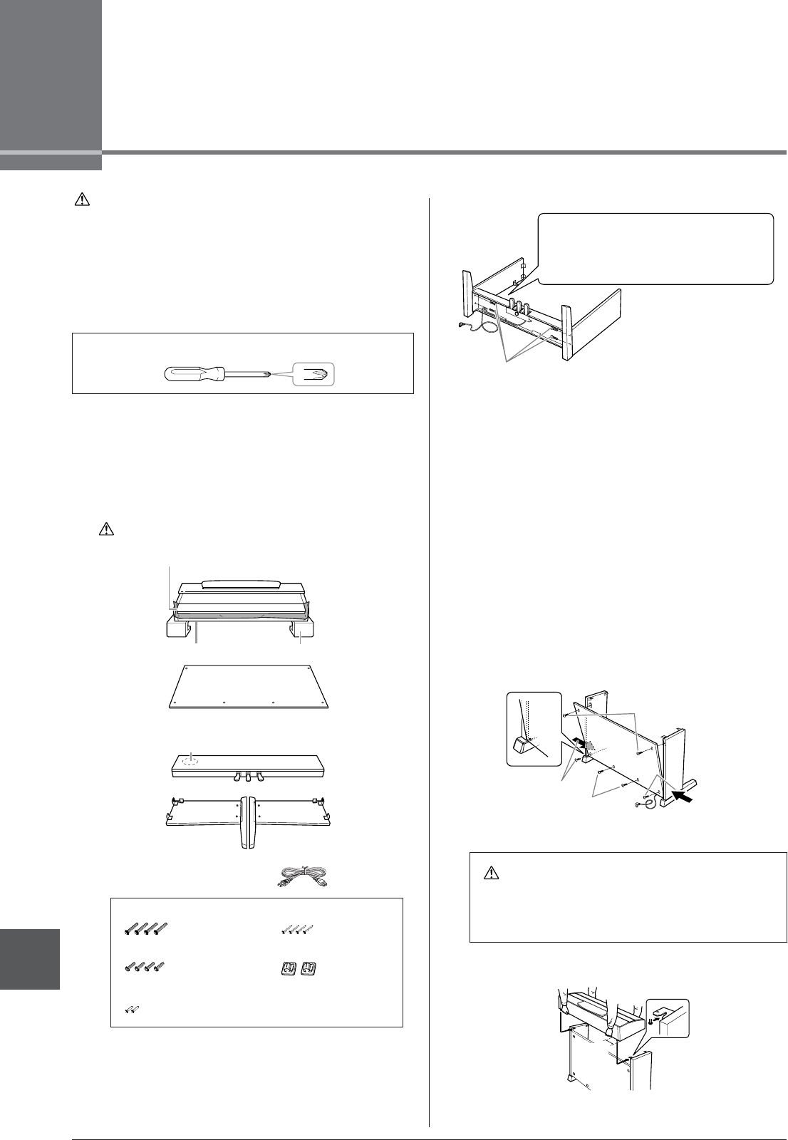
1 Open the package, take out marked “C” in the
illustration, take out the styrofoam pads, and
place the unit A on top of the pads.
Position the pads so that they will protect the headphone jack located
underneath the front left corner.
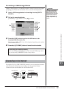
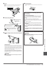
2 Attach C to D and E.
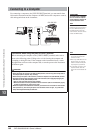
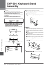
3 Attach B.
Depending on the model of digital piano you purchased, the surface
color of one side of the rear panel may be different from the other
side. In this case, position the rear panel so that the side of the surface
color similar to the side panel (left) and the side panel (right) faces
the player.
1 Place the lower side of B on each foot of D and E, then attach the
upper side to D and E.
2 Attach the top of B to D and E by finger-tightening the thin screws
(4 x 12mm).
3 While pushing the lower part of D and E from outside, secure the
bottom ends of B using two tapping screws (4 x 20mm).
4 Insert the other two tapping screws (4 x 20mm) into the other two
screw holes to secure B.
5 Securely tighten the screws on the top of B that were attached in
Step 3- 2).
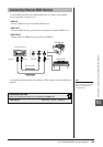
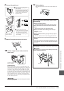
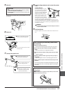
4 Mount A.
Be sure to place your hands at least 10 cm from either end of A when
positioning it.
Have a Phillips-head (+) screwdriver of the appropriate size ready.
AA
B
C
DE
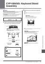
Main unit
Back panel
Side panel (left)
Side panel (right)
Assembly Parts
CAUTION
To prevent the key cover from accidentally opening during assembly, press
down on the key cover, making sure that the sheet (shown) remains in place.
Phones jacks Styrofoam pads
Pedal box
Bundled pedal cord inside
6 x 25 mm long screws x 4
6 x 16 mm short screws x 4
4 x 12 mm thin screws x 2
4 x 20 mm tapping screws x 4
Cord holders x 2
AC power cord
CAUTION
• Fingers can become pinched between A and C/D/E, be extra careful so
as not to drop A.
• Do not hold the keyboard in any position other than the position shown
in the illustration.
D
E
C
1 Untie and straighten out the bundled cord
attached to the bottom of the C. Don’t dis-
card the vinyl tie, you’ll need it later in
step 6.
2 Use the four 6 x 25 mm long screws to attach C. First attach
one side panel, then attach the other side panel.
25
3
3
1
4
B
E
D
A
At least
10 cm