


6
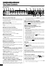
q Input Jack (INPUT HIGH, LOW)
Connect the guitar to this jack. Guitars with a high output level should
be connected to the LOW jack. Those with low output levels should be
connected to the HIGH jack.
* Switch the power OFF before connecting the guitar.
w Trim Control (TRIM)
Used to match the guitar’s output level to the pre-amp’s input level. (→
page 9.)
* TRIM level settings are not stored in memory.
e Output Level Control (OUTPUT)
Used to control the output volume of the power amp.
Sets the amount of output of sound created by the preamp’s GAIN,
MASTER, Tone Controls, etc. The volume is controlled without chang-
ing the tonal quality of the amp.
* Output level settings are not stored in memory.
* Has no affect on the level (volume) of the LINE OUT @4 jack.
r Gain Volume (GAIN)
Used to control the amount of distortion.
* Sound is not produced if the GAIN is set to 0, even when the MASTER VOL-
UME t is turned up.
When the Effect Mode is engaged, the GAIN knob is used to adjust the
tremolo’s SPEED setting. (→ page 9.)
t Master Volume (MASTER)
Used to control the overall volume of GAIN and tone control settings. It
also controls the output level of the preamp.
* Master level settings are stored in memory.
When the Effect Mode is engaged, the MASTER knob is used to adjust
the tremolo’s DEPTH setting. (→ page 9.)
y Tone Controls
(TREBLE, HIGH MID, LOW MID, BASS, PRESENCE)
Used to control the levels of their respective frequencies.
When the effect mode is engaged, it is possible to make the following
adjustments; (→ page 9.)
• TREBLE, HIGH MID, LOW MID → chorus’ SPEED, DEPTH, LEVEL
• BASS, PRESENCE → tape echo’s TIME, FEED BACK
u Reverb Volume (REVERB)
Used to control the amount of the reverb. (→ page 9.)
When the Effect Mode is engaged, the REVERB knob is used to adjust
the tape echo’s LEVEL setting. (→ page 9.)
i Amp Select Button/Amp Select Display
(LEAD 1, 2/DRIVE 1, 2/CRUNCH 1, 2/CLEAN 1, 2)
Used to select one of the eight preset amp types. The currently se-
lected amp type is shown on the display. (→ page 9.)
When the Utility Mode is engaged, these switches are used to switch
MIDI functions and the Speaker Simulator ON or OFF, etc. (→ page 12.)
!2!1 !6
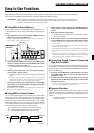
The Panel Controls
* When the Amp Select button is pressed, knobs r – y return to their preset
positions (GAIN and MASTER =7, Tone Controls all = 5). The position of
the REVERB knob does not change.
o Reverb Type Select Button (REVERB)
!0 Reverb Type Display Lamp (SPRING, HALL, PLATE)
Press the button to select the reverb type. The lamp corre-
sponding to the selected reverb type will light. (→ page 9.)
!1 Mode Select Button (MODE)
!2 Mode Display Lamp (AMP/EFFECT/UTIL.)
Displays the currently selected mode.
• AMP (Amp Mode)
Normal playing mode. All knobs and buttons on the panel function as
marked. (Dual function knobs and buttons will function according to
their lower indications.)
This mode is automatically engaged whenever a memory is recalled.
• EFFECT (Effect Mode) → page 9
The Effect (tremolo, chorus, tape echo) setting mode.
When in the Amp Mode, press the button once and quickly
release to enter the Effect Mode.
• UTIL. (Utility Mode) → page 12
This mode is used to set MIDI functions, switch Speaker Simulation
ON or OFF and set Volume Pedal position. When in the Amp Mode or
Effect Mode, press the button and hold for about one sec-
ond to enter the Utility Mode.
!3 Display
Displays Memory Numbers, Program Change Numbers, the MIDI Chan-
nel, etc.
!4 / Buttons
Increases or decreases the memory number by 1. Also, increases or
decreases values by 1. In the Utility Mode increases/decreases values
by 1 or sets the function ON/OFF. Values change continuously when
the button is pressed and held.
!5 Store Button (STORE)
Press this button to save current sound settings to internal memory. (→
page 10.) Also, used to carry out MIDI Bulk Out operations. (→ page
12.)
!6 Recall Button (RECALL)
Recalls the settings stored in memory. Use the / buttons to se-
lect a memory number (01 – 128), then press the button to
recall those settings from memory. (→ page 10.)
!7 Power Switch (POWER)
The power switch for the amplifier.
* To protect the speakers from possible damage, always set the OUTPUT e
volume to “0” before turning the power ON/OFF.
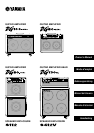
DG100-212A/DG80-210A/DG80-112A/DG130HA
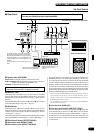
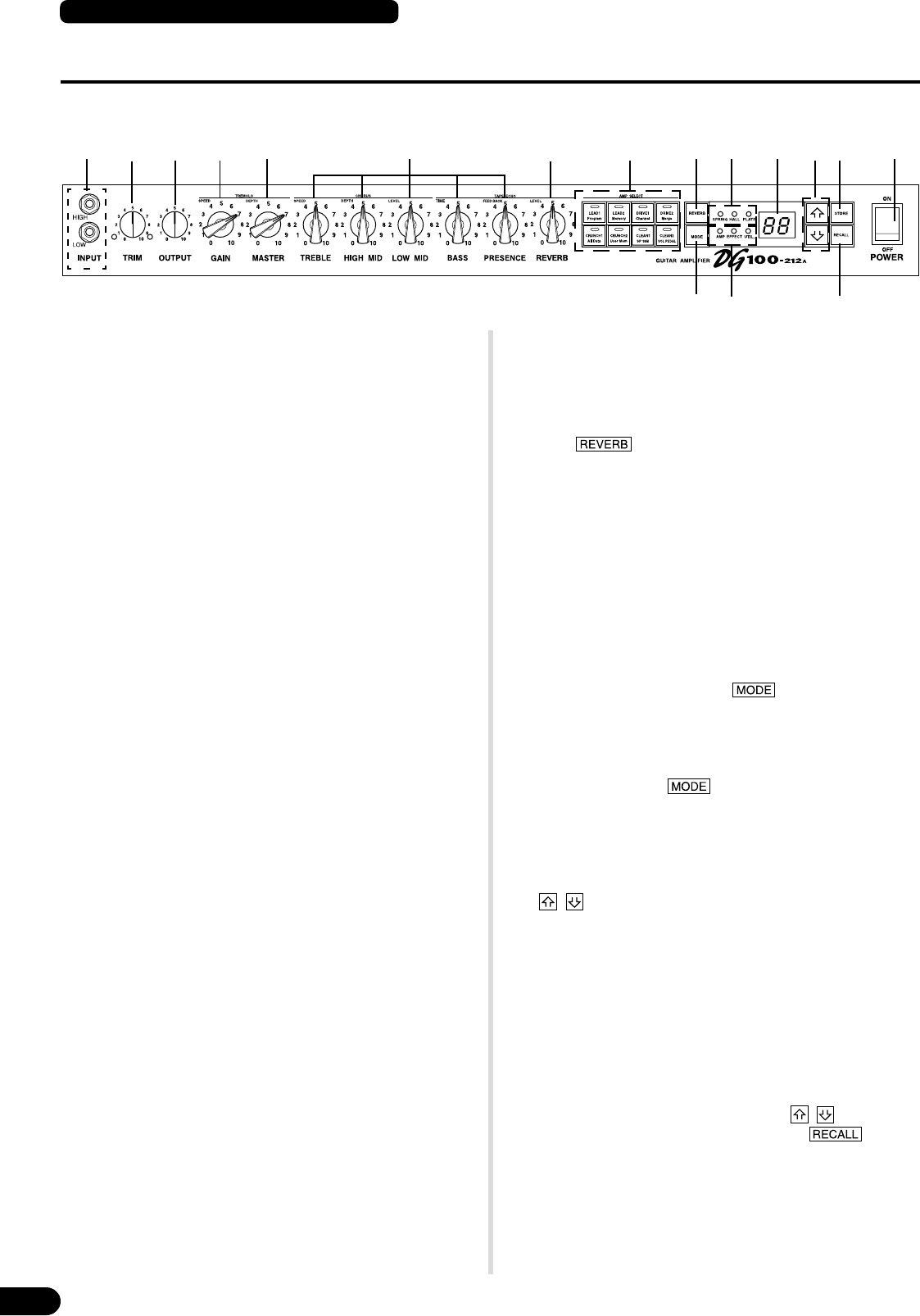
■ Front Panel
w e r t y uq i o !0 !3 !4 !5 !7
* The DG100-212A is shown in the illustration.