


5
A
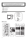
ENGINE ID A/B indicators
These indicators indicate whether the DSP1D/
DSP1D-EX is connected to the engine A or engine B
channel.
Indicator A lights up if the DSP1D/DSP1D-EX is con-
nected to the engine A channel jacks of the CS1D con-
trol surface (DIGITAL I/O jack A and CONTROL I/O
jack A). Indicator B lights up if the DSP1D/DSP1D-
EX is connected to the engine B channel jacks of the
CS1D control surface (DIGITAL I/O jack B and CON-
TROL I/O jack B).
Error indication
• If both ENGINE ID A and B indicators are flash-
ing:
→
There is a malfunction in the internal board
(PDB, GDB, IDB1/2, EDB, EMB, or CIB). Or
the necessary board does not exist.
• If either ENGINE ID A or B indicator is flashing:
→
During the Mirror mode operation, the
ENGINE ID indicator for the unused DSP1D/
DSP1D-EX flashes, indicating that the unit is in
standby mode.
→
If Indicator A is flashing, unit A is in standby
mode. If Indicator B is flashing, unit B is in
standby mode.
B
CONTROL I/O 1/2 indicators
These indicators indicate which one of two CON-
SOLE 1, 2 IN/OUT jacks (
8
) on the rear panel is cur-
rently effective.
Error indication
• If the CONTROL I/O 1 indicator is flashing:
→
Communication between the CS1D control
surface and the DSP1D is not established.The
CONSOLE 1, 2 IN OUT jacks or the PC CON-
TROL port is not connected correctly.
C
INPUT CONFIGURATION 48CH/96CH
indicators
These indicators indicate how many input channels
are currently available. On the DSP1D, the 48CH
indicator lights up. On the DSP1D-EX, the 96CH
indicator lights up.
Error indication
• If the INPUT CONFIGURATION 48CH is flashing:
→
The signal is not locking to the word clock.
D
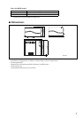
POWER ON/OFF switch
Use this switch to turn the power to the DSP1D/
DSP1D-EX on or off. When the power is turned on,
the indicators
1
-
3
light up.
E
MIDI IN/OUT/THRU connectors
These connectors are used to transmit and receive
Program change messages, MMC, and other MIDI
messages among external MIDI devices.
F
PC CONTROL RS-232-C/USB ports
Connect these ports to a PC that runs Windows 95 or
Windows 98 to control the PM1D system from the
PC. Use a D-sub, 9-pin cross cable (female to female)
to connect the RS-232-C port to the serial (COM)
port on the PC. The USB port is provided for future
system expansion, but it is not operative in the current
software version.
G
WORD CLOCK IN jack, 75
Ω
ON/OFF
switch, and WORD CLOCK OUT jack
The WORD CLOCK IN jack is used to provide word
clock to the PM1D system from the connected exter-
nal device, such as a clock generator. Use the WORD
CLOCK OUT jack to provide the word clock to the
connected external device from the PM1D. Use a BNC
cable with an impedance of 75
Ω
for the WORD
CLOCK IN/OUT jacks.
The WORD CLOCK ON/OFF switch is used to termi-
nate the word clock connection. Basically, if the
DSP1D/DSP1D-EX is the last device of the word clock
chain, or if nothing is connected to the WORD
CLOCK IN/OUT jacks, set this switch to ON.
H
CONSOLE 1, 2 IN/OUT jacks
These jacks are connected to the CONTROL I/O
CONSOLE jacks of the CS1D control surface to trans-
mit or receive control signals. For connection, use a
genuine Yamaha cable or a BNC cable with an imped-
ance of 50
Ω
.
I
REMOTE RS-422 connector
This D-sub 9-pin connector is used to control a con-
nected tape recorder or a hard disk recorder. Serial
commands can be transmitted through this connector
to play or stop such a recorder.
This connector is provided for future system expan-
sion, but it is not operative in the current software
version.
J
GPI connector
This connector is used to connect an external device
that supports GPI (General Purpose Interface), such
as a video editor to control the external device from
the PM1D system or to perform certain functions of
the PM1D system while controlling from the external
device. You can connect a custom-made external
switch here.
This connector is provided for future system expan-
sion, but it is not operative in the current software
version.
Note:
When you turn on the power to the DSP1D/
DSP1D-EX and the CS1D, and communication
between the DSP1D/DSP1D-EX and the CS1D is
established, one of these two indicators lights up. If
neither one lights up, check the connection of the
CONSOLE 1, 2 IN OUT jacks on the rear panel.