


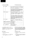
4-6. Data is not accepted from the panel switches and keys while the sub-CPU C2 line is
low.
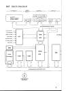
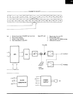
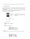
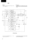
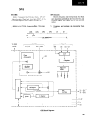
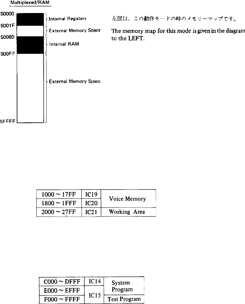
5. Main CPU Operation
The main CPU mode is set by externally initializing lines P20~P22. When “L, L, H” is applied to
the P20~P22 lines and latched into the CPU on the rising edge of RES, the Extended Multiplex
Mode is selected.
In this mode, P40 ~ P47 function as address lines. The lower address bits are multiplexed with the
data on lines P30 ~ P37, and are separated by the address strobe signal SCI.
P20 ~ P24 and P10 ~ P17 function as I/O lines.
6. RAM
M5M511BP-15 X 8-bit CMOS RAM.
7. ROM
2764 8K X 8-bit NMOS EROM
8. LED
The LED display is created via software. The LEDs are lit by data latched from the
main CPU.