


282
Appendix
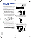
How to Install the
EXDGO1 in the EX5/7
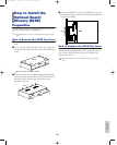
Necessary Items
• EXDGO1 (Digital Output Board) x 1
• Flat cable x 1 (included in the EXDGO1 package)
Installation
You can install the EXDGO1 after removing the
optional board cover. For more information on
removing the optional board cover, see How to Remove
the Optional Board Cover.
If the ASIB1 (SCSI Interface Board) is already
installed, it must first be removed before proceeding.
If you want to install the two boards simultaneously,
first install the EXDGO1.
When installing the optional board (from when you
remove the cover to when the cover is replaced
securely) all operations must be done with the power
cord disconnected.
The procedure for installing the EXDGO1 is the same
as for the EXIDO1. Refer to How to Install the
EXIDO1 in the EX5/7.
For information on Word Clock settings, see Utility mode
(page 277).
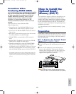
When the EXDGO1 is properly installed, L and R
signals will be output digitally.
When connecting the EXDGO1 (Digital Output AES/EBU
[XLR] jack) and an external audio device, use the XLR
cable with the impedance characteristics, 110Ω
When receiving word clock from an external audio device,
you are required to connect the EXDGO1 (Word Clock In
[BNC] jack) and the external audio device. In this case, use
the BNC connector/coaxial cable with the impedance
characteristics, 75Ω
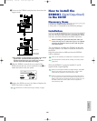
How to Install the ASIB1
in the EX5/7
Necessary Items
• ASIB1 (SCSI Interface Board) x 1
• SCSI cable (Flat cable 50P; length: 280mm) x 1
(included in the ASIB1 package)
• Cutting pliers or scissors (to cut a cable)
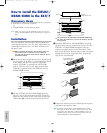
When you open the package of the ASIB1 board, you
will find two SCSI cables connected to the ASIB1,
and two (2-pin) power cables, one is plugged to the
ASIB1 and the other is left unplugged. To install the
ASIB1 into the EX, only the short (280mm long)
SCSI cable is used. First, it is necessary to remove
the long (480mm long) SCSI cable and 2-pin power
cable from the ASIB1 board.
Installation
You can install the ASIB1 after removing the optional
board cover. For more information on removing the
optional board cover, see How to Remove the Optional
Board Cover.
When two boards are installed simultaneously such as
the ASIB1 and EXIDO1 (or EXDGO1), first install the
EXIDO1 (or EXDGO1).
When installing the optional board (from when you
remove the cover to when the cover is replaced
securely) all operations must be done with the power
cord disconnected.
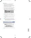
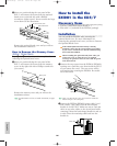
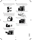
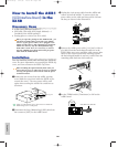
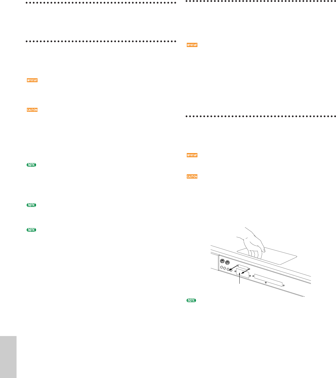
1 Remove the two screws from the ASIB1 opening cover (hold
the cover from inside the EX5/7 as you remove the cover).
The two screws will be used again when securing the ASIB1.
Be careful not to lose them.
After you take off the cover, do not leave it inside the
EX5/7 and put it in a safe place.
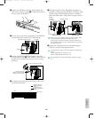
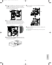
2Disconnect the long (480mm long) SCSI cable from
the connector (CN1) on the ASIB1 board.
Opening cover
Option/E/qx 5/21/98 11:58 AM Page 282