


F11/F01 Owner’s Manual
62
ENGLISH
Keyboard Stand Assembly
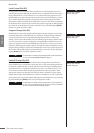
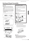
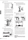
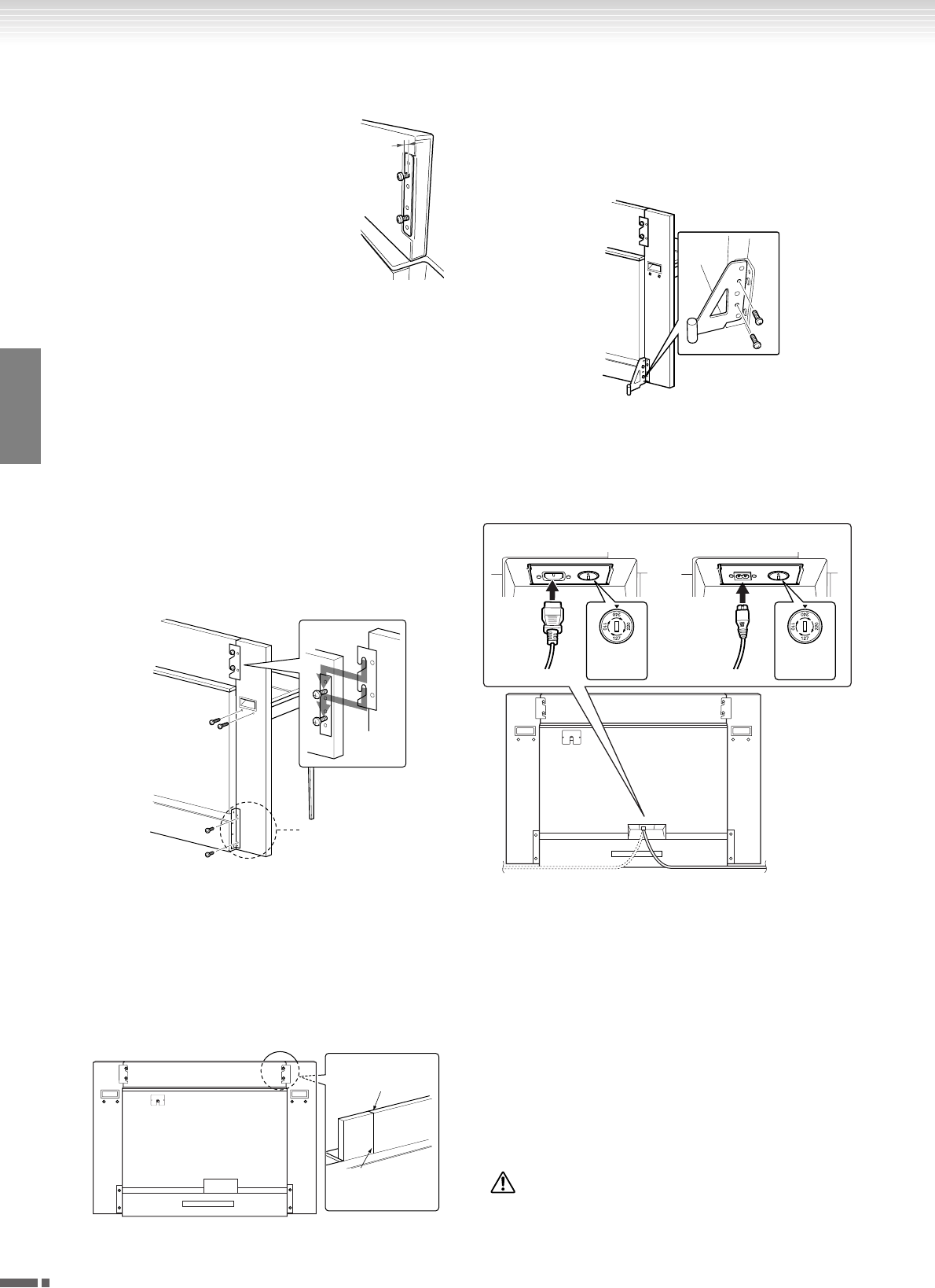
2 Install the rear panels (left and right).
1 Attach two short screws (6 ×
14mm) to each edge of the
rear panel (center) using
your fingers so that the
screw threads project about
10mm from the surface.
Make sure that the screws
will not loosen and fall out
of the holes.
2 Make sure that the screws you finger-tightened
in Step 1 have not loosened. Then position the
handhold of the rear (left) panel toward the
rear, and hook the bracket of the rear (left)
panel onto the projecting screws as shown in
the illustration 2. When doing so, be careful
that the bracket does not scratch the rear panel
(center).
3 Align the holes located under the handhold on
the rear panel (left) with the holes on the main
unit, then tighten two long screws (6 × 45mm)
to secure the panel to the unit.
4 Lightly tighten two short screws (6 × 14mm)
into the bracket on the bottom of the unit to
secure the panel to the unit.
5 Follow the same steps to install the rear panel
(right).
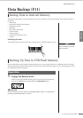
3 Fasten the rear panels securely.
Tighten the screws securely in the order shown in
the illustration. Be careful not to permit mis-
aligned levels on the front surface, or a gap on the
top surface of rear panels (center, left, and right).
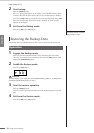
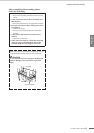
4 Attach the fall-prevention bracket.
Align the second and fourth holes on the fall-pre-
vention bracket with the bracket holes on the bot-
tom of the unit, then secure the bracket using two
short screws (6 × 14mm).
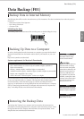
5 Set the voltage selector and connect the
power cord.
Insert the AC power cord plug into the [AC
INLET] connector on the rear of the unit.
Voltage Selector
Before connecting the AC power cord, check the setting
of the voltage selector which is provided in some areas.
To set the selector for 110V, 127V, 220V or 240V main
voltages, use a “minus” screwdriver to rotate the selector
dial so that the correct voltage for your region appears
next to the pointer on the panel. The voltage selector is
set at 240V when the unit is initially shipped. After the
proper voltage has been selected, connect the AC power
cord to the AC INLET and an AC wall outlet. A plug
adaptor may be also provided in some areas to match the
pin configuration of the AC wall outlets in your area.
WARNING
An improper voltage setting can cause serious
damage to the instrument or result in improper
operation.
10mm
3
4
2
Position the bracket to
the rear of the rear
panel (left).
22
3
3
11
Edges must
be flush.
Do not allow
a gap.
(F11) (F01)
Voltage
Selector
Voltage
Selector