


132
Voice Mode
■ Pitch Coarse
Adjusts the length of the delay in semitones. A
setting of “0” produces the delay length
corresponding to the pitch of C3 = 261.63Hz. In
general this should be adjusted to the basic pitch of
the input signal.
❏ Settings: –64~0 (C3)~+63
■ Pitch Fine
Adjusts the length of the delay in increments of
cents.
❏ Settings: –50~0~+50
■ KeyFollow
Sets the KeyFollow for the delay length. This
KeyFollow function controls the length of the delay
in accordance with the notes played on the keyboard.
When set to “+32,” the KeyFollow functions at
100% and the length of the delay moves in inverse
proportion to the pitch played on the keyboard.
When set to a value of “0” the length of the delay is
fixed.
❏ Settings: –32~0~+64
■ EG Depth (Envelope Generator Depth)
Sets the EG depth that affects the delay length.
❏ Settings: –64~0~+63
■ EG Depth Vel (Envelope Generator Depth
Velocity)
Sets the velocity sensitivity for the EG depth. The
EG depth can be controlled by the velocity at which
the note played on the keyboard.
❏ Settings: –64~0~+63
■ Attack Time
Sets the amount of time from when the note is
played to the maximum level.
❏ Settings: 0~127
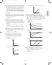
■ Attack T.Kf (Attack Time KeyFollow)
Sets the KeyFollow for the Attack Time. This
KeyFollow function controls the attack time in
accordance with the notes played on the keyboard.
When set to a positive value, the higher the note
played on the keyboard, the shorter the attack time
becomes. When a negative value is set, the lower the
note played, the shorter the attack time becomes.
❏ Settings: –64~0~+63
■ EG Time Kflw (Envelope Generator Time
KeyFollow)
Sets the KeyFollow for the EG Time. This KeyFollow
function controls the amount of the EG time in
accordance with the notes played on the keyboard.
When set to a positive value, the higher the note
played on the keyboard, the shorter the EG time
becomes. When a negative value is set, the lower the
note played, the shorter the EG time becomes.
❏ Settings: –64~0~+63
■ Balance
Sets the mix balance for the original input signal and
the delayed signal. A setting of “0” means that only
the original input signal is produced. When set to a
positive value, the difference between the input
signal and the delayed signal is produced and the
usual pulse width modulation effect will be obtained
at the value of “+32.” When a negative value is set,
the input signal and the delay signal are added and a
chorus effect is obtained at the value of “–32.”
❏ Settings: –32~0~+32
■ Pan
The same as the one in the EP Pickup. See page 126
for information.
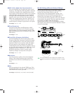
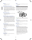
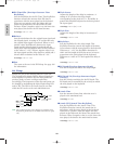
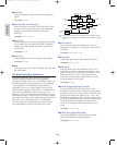
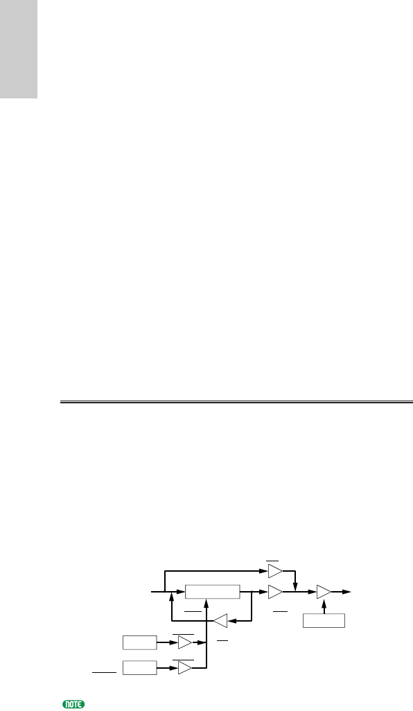
05: Flange
Flange lets you get the flanging effect for each note.
The original input signals and the delayed signals are
mixed together to produce dips and their feedbacks
produce peaks, to create a unique comb filter,
accordingly. The frequencies of the dips and peaks can
be changed by modulating the delay length using LFO
and/or EG. The LFO is set for all notes at one time
while the EG can be set for each individual note.
The underlined items in the diagram are available as the
Destination parameters for the FDSP Controller set (page
141).
Delay
Dry
Wet
FB
Input Output
EG
LFO
note dependent
Attack/
Decay/
Sustain
Release
Depth
Depth
Speed
Wave
Pitch
coarse/fine
EG
Voice/E.qx 5/21/98 11:31 AM Page 132