


280
Appendix
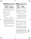
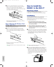
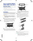
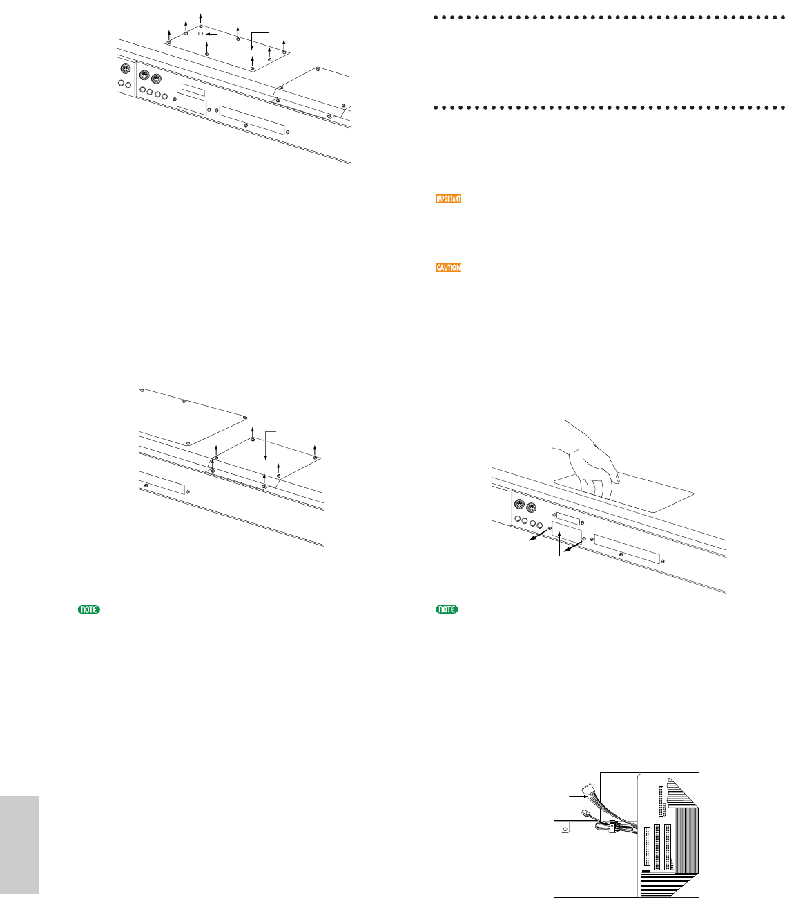
3Move to a position facing the rear panel of the
EX5/7, and remove the screws from the optional
board cover on the left side with a Phillips
screwdriver (eight screws). Do not remove the large
screw shown in the illustration.
Remove the optional board cover and you will see
the installation connectors.
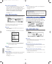
How to Remove the Memory Cover
(EXFLM1, DRAM SIMM)
Steps 1 and 2 are the same as those explained in
removing the optional board cover.
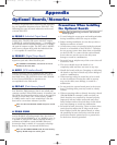
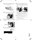
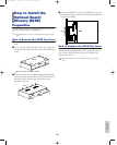
3Move to a position facing the rear panel of the
EX5/7, and remove the screws from the memory
cover on the right side with a Phillips screwdriver
(six screws).
Remove the memory cover and you will see the
installation sockets.
For information on how to handle the EX5R, see page
285.
Memory cover
Do not remove this screw.
Optional board cover
Memory cover
Rear panel
How to Install the
EXIDO1
in the EX5/7
Necessary Items
• EXIDO1 (Individual Output Board) x 1
• Flat cable x 1 (included in the EXIDO1 package)
Installation
You can install the EXIDO1 after removing the
optional board cover. For more information on
removing the optional board cover, see How to Remove
the Optional Board Cover.
If the ASIB1 (SCSI Interface Board) is already
installed, it must first be removed before proceeding.
If you want to install the two boards simultaneously,
first install the EXIDO1.
When installing the optional board (from when you
remove the cover to when the cover is replaced
securely) all operations must be done with the power
cord disconnected.
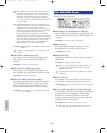
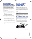
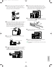
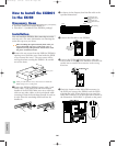
1Remove the two screws from the EXIDO1/EXDGO1
opening cover (hold the cover from inside the EX5/7
as you remove the cover). The two screws will be
used again when securing the EXIDO1. Be careful
not to lose them.
After you take off the cover, do not leave it inside the
EX5/7 and put it in a safe place.
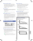
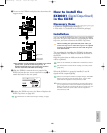
2Remove the EXIDO1/EXDGO1 power cable (1 red
and 4 white, 5 pin cable) from the hook-shaped
bundle tie in the EX5/7. Make sure not to catch the
cable on any other cables or the circuit board while
removing it from the hook-shaped bundle tie and set
it aside. Place the remaining cable back into the
bundle tie.
Power cable
Opening cover
Option/E/qx 5/21/98 11:58 AM Page 280