


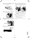
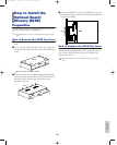
3Support the EXIDO1 with your hand and use the
two screws removed in step 1 to attach the board to
the rear panel of the EX5/7.
4Use the two screws that are attached to the EXIDO1
to attach the board to the EX5/7 metal fitting.
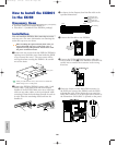
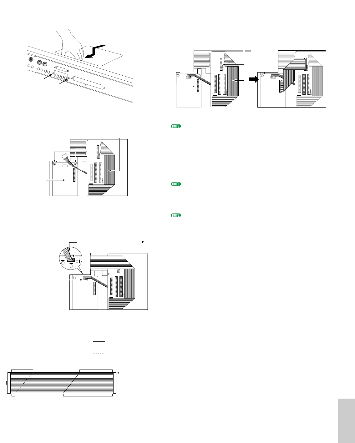
5Connect the EXIDO1/EXDGO1 power cable that
was set aside in step 2 to the EXIDO1 connector. Be
careful not to connect the connector in the wrong
direction.
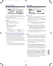
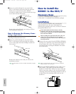
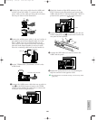
6As shown in the diagram, bend the flat cable to the
specified dimensions.
80mm
Indicates that the cable
should be folded upwards
at this line.
Indicates that the cable
should be folded downwards
at this line.
5mm
50mm35mm
Blue marking
Connect the connector
(Make sure that the connector
is facing the correct direction)
Line up the red cable with this mark .
Fix the board with the two screws.
FDD cable
EXIDO1
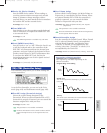
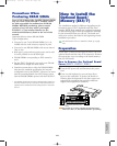
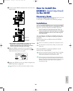
7Check the location of the DGO/IDO connector in
the EX5/7 and connect the EXIDO1 and EX5/7 with
the flat cable. The DGO/IDO connector is hidden
under the FDD cable. “DGO/IDO” is printed on the
panel.
When you lift up the FDD cable to connect the flat cable
to the DGO/IDO connector, the FDD cable may
inadvertently be pulled out of the connector. Make sure
that the FDD cable is securely connected after connecting
the optional board.
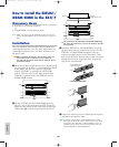
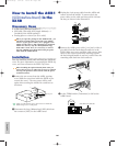
8Replace the optional board cover by following the
steps for removal in the opposite order.
The Individual Output jacks to be added are numbered as
follows.
• EX5: INDIVIDUAL OUTPUT 3~6
• EX7: INDIVIDUAL OUTPUT 1~4
For information on Individual Output settings, see page
19.
DGO/IDO connector
FDD cable
Before connection After connection
Connector on
the EXIDO1
281
Appendix
Option/E/qx 5/21/98 11:58 AM Page 281