


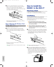
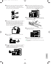
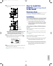

3Unplug the 2-pin power cable from the ASIB1 and
remove it from the ASIB1. To remove the 2-pin
power cable, cut the cable and then pull it out from
the hoop as shown in the illustration.
4Remove the ASIB1 power cable (1 red and 1 white, 2
pin cable) from the hook-shaped bundle tie in the
EX5/7. Make sure not to catch the cable on any
other cables or the circuit board while removing it
from the hook-shaped bundle tie and set it aside.
Place the remaining cable back into the bundle tie.
5Set the TERM switch (Terminator) to ON on the
ASIB1 board.
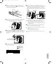
6Connect the ASIB1 power cable that was set aside in
step 4 to the CN2 connector (next to the TERM
switch) on the ASIB1. Be careful not to connect the
connector in the wrong direction.
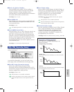
ON TERM OFF
ON TERM OFF
ON TERM OFF
Short (280mm long) SCSI cable
Power cable
E
RM OFF
2cm
E
RM OFF
Cut here
Pull out
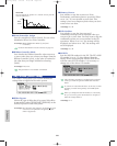
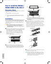
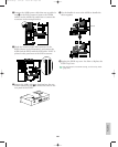
7Check the location of the SCSI connector in the
EX5/7 (shown in the illustration) and connect the
ASIB1 and the EX5/7 with the SCSI cable. “SCSI” is
printed on the panel next to the SCSI connector.
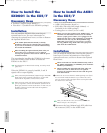
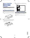
8Support the ASIB1 with your hand and use the two
screws removed in step 1 to attach the board to the
rear panel of the keyboard.
9Arrange the SCSI cable so it sits in between the
ASIB1 and the panel.
)Replace the optional board cover by following the
steps for removal in the opposite order.
For information on SCSI ID settings, see the Utility mode
(page 276).
ON TERM OFF
ON TERM OFF
SCSI connector
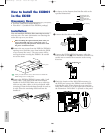
FDD cable
283
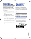
Appendix
Option/E/qx 5/21/98 11:58 AM Page 283